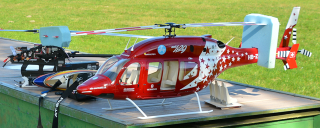
Die Bell 429 von ROBAN/Scaleflying.de
Bericht:
Wie es dazu kam

Hier geht es um mein Exemplar der ROBAN Bell 429 und wie es mir damit ergangen ist. Vielleicht hilft das jemandem, so wie es mir immer hilft, Berichte anderer Modellflieger zu lesen.
Einige allgemeine Informationen zu diesem Modell gibt es hier auch, einiges ist im Internet zu finden (siehe "Weiteres"), aber das meiste ist das, was ich gerne gelesen hätte, bevor ich diesen Hubschrauber zusammengebaut habe – zusätzlich zu der dennoch wichtigen Anleitung von ROBAN.
Manches trifft sicher auch auf die anderen Modelle aus der "SuperScale"-Reihe von ROBAN zu. Sie sind alle ähnlich aufgebaut und enthalten die gleiche 800er Mechanik.
Nachdem ich 2020 mit meiner HIROBO Schweizer 300 sechs schöne Flugstunden angesammelt hatte, wir aber im nächsten Corona-Lockdown saßen, wollte ich einen noch größeren Modellhubschrauber haben – wahrscheinlich aus reiner Gier. Er sollte mindestens vier Blätter am Hauptrotor haben und wieder "scale" sein, also nicht für Kunstflug – sozusagen altersgerecht (mittlerweile noch wichtiger).
Eine Hughes 500 hätte mir immer noch gut gefallen, aber ihr Rumpf ist im Verhältnis zum Hauptrotor noch größer als bei der Schweizer 300. Das sähe nicht nur massig aus, sondern würde – mit dem besonders hohen Landegestell – sehr hoch werden. Dann hätte ich wohl Probleme beim Verladen ins Auto (dachte ich zumindest damals, aber das war falsch).
Etwas "schlankeres" musste es also sein – wie die Bell 429. Die von Air Zermatt kannte ich von Fernsehen und YouTube und sie gefiel mir ausnehmend gut (und offenbar nicht nur mir, sondern vielen). Ein Vereinskollege, der den 700er Tiger von ROBAN/Scaleflying.de besitzt, brachte mich dann auf das Modell. Er hat mir dringend zugeraten, nicht die 600er, sondern die 700er B 429 zu nehmen (und hätte mir zu einer 800er geraten, wenn es die gegeben hätte).
Als das Paket dann so bei mir auf dem Teppich lag, bekam ich doch einen Schrecken, was ich mich da getraut hatte. Aber wenn der Heli erst einmal gebaut ist, würde ich mich wohl an seine Größe gewöhnt haben. Außerdem sieht er auf dem Flugplatz nicht mehr so mächtig aus, wie ich von dem 700er Tiger und einem 800er Airwolf weiß – und größer fliegt schöner, da hatte ich keine Sorge.
Die Größe ist also als 700 angegeben, wobei die neuen Rotorblätter 720 mm lang sind – gibt 1,60 m Rotordurchmesser (1,56 m laut Anleitung). Die Mechanik wird als 800er bezeichnet, weil sie für diese Größe gemacht ist (und dies ist ein 4-Blatt-Rotor), und ein 750er Motor mit 450 kv wird in der Anleitung genannt. Ein 700er Motor (natürlich mit 12s LiPo-Akku) passt allerdings mit seinem Durchmesser gerade gut hinein und reicht laut Scaleflying.de auch gut aus (dies ist ein Scale-Heli), ebenso wie die von Scaleflying.de empfohlene Rotordrehzahl von 1100 U/min. Das Gewicht ist mit 8 oder 9 kg angegeben, je nachdem wo man nachliest. Wie zu vermuten war, stellte sich 9 kg als realistisch heraus und 8 kg als absolute Untergrenze. Die Maßangaben in der Anleitung stimmen, der Maßstab ist 1:7 – etwas kleiner als bei der HIROBO Schweizer 300 (1:6,32).
Auf YouTube habe ich ungefähr 40 Videos von der ROBAN Bell 429 gefunden (siehe "Weiteres"). Wenn dort der Antrieb erwähnt wird, dann ist es meist ein größerer Motor (750 oder sogar 800) mit höherem kv und eine höhere Rotordrehzahl. Das kam mir etwas übertrieben vor (mein Heli soll keine Lasten schleppen) und ich vertraute eher den Empfehlungen von Scaleflying.de, die mir sogar auf Anfrage per E-Mail noch einmal bestätigt wurden (danke!). Um aus Vertrauen Gewissheit zu machen, wurden Antrieb (siehe unten) und Rotoren des Modells im Flugsimulator abgebildet (siehe unten) – und ja, die Angaben sind richtig.
Was mir etwas Sorgen machte war meine Unerfahrenheit. Zwar weiß ich, wie alles funktioniert, aber ich habe keine praktische Erfahrung. Die HIROBO Schweizer 300 war eine gute Übung, aber da war alles perfekt vorbereitet und beschrieben. Die Anleitung zur B 429 hatte ich vor dem Kauf schon von der entsprechenden Webseite von Scaleflying.de heruntergeladen. Sie kam mir recht kurz und etwas verwirrend vor und das bestätigte sich, als der Heli geliefert war. Drei zusätzliche Zettel enthielten wichtige Informationen, die in der Anleitung (Version 2.0 – Mai 2016) noch nicht enthalten sind, aber das war es auch.
Auf dem YouTube-Kanal von Scaleflying.de gab es vier nützliche Videos, in denen die Montage einer 800er-Mechanik gezeigt wurde. Besonders wurde darauf hingewiesen, daß die Mechanik vormontiert ist, aber komplett zerlegt und dann mit Sicherungsmittel wieder zusammengebaut werden soll. Außerdem soll das Zahnflankenspiel der Kegelradgetriebe zum Heckrotor geprüft und gegebenenfalls mit (im Bausatz enthaltenen) Unterlegscheiben eingestellt werden (und in dieser neueren Version auch das Spiel des Schrägkugellagers an der Hauptrotorwelle).
Was mich gleich irritierte war der Hinweis, daß Schrauben mit Wärme gelöst werden müssen, wenn sie durch Sicherungsmittel zu fest sitzen. Mein Vereinskollege meinte, die Vormontage spart die Verpackung der vielen Einzelteile und die genaue Beschreibung ihrer Montage. Das leuchtete mir ein, aber warum war dann schon Sicherungsmittel verwendet und – wie sich später herausstellte – die Winkelgetriebe (wie auch das Schrägkugellager) schon mit Unterlegscheiben eingestellt und gefettet? Für mich sah es eher nach Haftungsausschluß des Vertreibers Scaleflying.de aus (der damals sogar Anteile an ROBAN hielt) und das hat mich zunächst sehr gebremst.
Im Rückblick ist diese Angelegenheit sogar noch zweifelhafter. Ich hatte die deutsche Anleitung durchgearbeitet, die ich von Scaleflying.de heruntergeladen hatte und die (auf Papier) auch dem Baukasten beilag. Erst später habe ich die originale englische Anleitung heruntergeladen und fand dort (auf Seite 4) die Sätze "Factory pre-assembled components have been assembled with all the required thread lock and lubricants, and have passed quality control. It is not necessary to disassemble and re-assemble them." (Ab Werk vormontierte Baugruppen wurden mit aller nötigen Schraubensicherung und Schmierung montiert und sind qualitätsgeprüft. Es ist nicht nötig, sie auseinanderzunehmen und wieder zusammenzusetzen.) Vermutlich hatte Scaleflying.de die Anleitung ins Deutsche übersetzt und absichtlich diese beiden Sätze ausgelassen (und den Raum leer gelassen). Im Video betonte Herr Illig, daß man die ganze Mechanik auseinandernehmen und mit Schraubensicherung wieder zusammensetzen sollte. Es ist nicht klar, was genau jeweils von ROBAN und Scaleflying.de gemeint war, und wahrscheinlich liegt die Wahrheit irgendwo in der Mitte.
Zusammenbau
Der Hubschrauber ist günstig für das, was er bietet, aber er kostet trotzdem eine Menge Geld. Deshalb wurde er zum Weihnachtsgeschenk erklärt und zunächst nicht ausgepackt. Die verbleibende Zeit wurde genutzt, um die nötigen (und insgesamt noch ein Viertel mehr als der Bausatz kostenden) Komponenten zu beschaffen: Motor, Regler (noch ohne Kondensatoren) mit USB-Adapter, Sicherheitsschalter für Antriebsakku (noch ohne Widerstand) mit Empfängeradapter, vier Servos, Kreiselsystem ("flybarless"), Empfänger, Telemetrie (GPS, zwei Spannungssensoren, Aufzeichnungsgerät), Schalter/Mischer für zwei Empfängerakkus, Kabel und Stecker – aber noch keine Akkus. Am ersten Weihnachtstag wurde dann ausgepackt und als erstes die Mechanik untersucht.
Mechanik

Von rechts: Mechanik, eingeschweißt die Teile des Motorwellen-Stützlagers, Hauptrotorkopf, Heckrotor mit Winkelgetriebe, Heckrohr mit Heckwelle verpackt, Haupt- und Heckrotorblätter – wunderbar!
Besonders gefiel mir, daß ich die neueste Version bekommen habe, in der noch einiges verbessert wurde: Stützlager für die Motorwelle, schrägverzahntes Hauptgetriebe, Schrägkugellager für die Hauptrotorwelle, längere Hebel für die Taumelscheibe, dadurch längere Hebelarme an den Servos, Blattanlenkungen ohne Taumelscheibenmitnehmer, längere Rotorblätter, Hauptrotorblätter mit S-Schlag-Profil.
Das sollte ich also alles auseinandernehmen? Die Freude wich Ärger. Deshalb habe ich mich oft gar nicht mit dem Heli befassen wollen. In Zeiten, in denen ich gelassener war, habe ich die Videos von Scaleflying.de angeschaut, über die Montage von Getrieben gelesen und immer wieder Mechanik und Rotorköpfe untersucht.
Zwischen diesem Bild und dem nächsten liegen schließlich neun Monate. Im Sommer ging es dann aber ganz schnell. Die Rotorköpfe wurden kontrolliert und erwiesen sich als fest (mit Sicherungsmittel) verschraubt, während die Schrauben an den Carbon-Seitenteilen kein Sicherungsmittel hatten. Die Mechanik wurde teilweise demontiert, um das Winkelgetriebe umzubauen, dann mit Sicherungsmittel wieder zusammengebaut.

Das Ergebnis gefällt mir sehr gut, auch wenn ich immer noch unsicher bin – wegen der Schraubensicherung, des Getriebespiels, des Lagerspiels. Das Heckrohr liegt wirklich etwas schräg; so läuft es dann in der Hecktüte, wenn die Kabine des Helis waagerecht liegt (im Vorwärtsflug). Der Rotormast ist dann um den gleichen Winkel nach vorne gekippt (weniger als beim Original, wo der Rotormast schon am Boden um 5° nach vorne gekippt ist). Die 800er-Mechanik (genannt SM2.0 Mechanics) von ROBAN ist im Prinzip immer gleich, das heißt in deren SuperScale-Modellen, aber die Carbon-Seitenteile sind für jedes Modell anders (und einige Wellen auch). Bei der B 429 liegt eben das Heckrohr bezogen auf die Kabine etwas schräg und relativ hoch. Hier gibt es auch kein 45°-Winkelgetriebe im Heckrohr wie beim Tiger.
Übrigens sind die drei Halter für die Heckrotoranlenkung nicht nur einfach aufgeschoben. Scaleflying.de gab den Hinweis, daß man dann noch einen Kabelbinder zwischen dem Ring des Halters und dem Rohr durchziehen kann. Man zieht, bis er mit seinem Verschluß an einer Seite an den Ring stößt, und schneidet den langen Überstand an der anderen Seite ab. Nun ist der Halter geklemmt und rutscht und dreht nicht.

Die beiden Abstrebungen des Heckrohrs sind aus Carbon, die Beschläge aus Aluminium. In einem der Videos von Scaleflying.de wurde erwähnt, daß sie bei jedem Modell anders angebracht werden und man an Unterlegscheiben die vorgesehenen Schrauben an den Seitenteilen erkennt. So war es auch und das Ganze passt so durch die Öffnung hinten im Rumpf, also wird es wohl stimmen.
Der Motor treibt einen Zahnriemen, den man seitlich aus dem Rahmen hervorkommen sieht. Über der großen Zahnriemenscheibe sitzt ein stählernes Ritzel, welches das hier sichtbare weiße Kunststoffzahnrad (Großrad) und damit die Hauptrotorwelle antreibt.
Die drei Taumelscheibenservos sind jeweils mit einem 90°-Umlenkhebel in klassischer 120°-Anordnung angelenkt. In dieser neuen Ausführung sind die drei Umlenkhebel länger als früher und die drei Schubstangen zum Servo alle gleich lang.

Der KONTRONIK Pyro 700-45 (kv 450) wurde wegen der guten Erfahrungen mit dem Pyro 600-09 (kv 930) in meiner HIROBO Schweizer 300 gewählt. Mit ungefähr halb so großem kv ist er für 12s statt 6s LiPo vorgesehen.
Ein stärkerer Motor ist laut Scaleflying.de nicht nötig (finde ich jetzt auch, siehe unten). Wenn ich einen solchen denn wollte, dürfte er aber keinen wesentlich größeren Durchmesser (als diese 51 mm) haben, damit er noch in die Ausbuchtung des Rahmens passt.
Man muß sich bei der Montage des Motors entscheiden, ob die sehr steifen Anschlußdrähte (nicht -kabel) schräg nach vorne links oder rechts zeigen sollen. Das hängt davon ab, wie der Regler davor angebracht werden soll (siehe unten).
Der Motor sitzt auf einer Art Schlitten, der mit zwei Schrauben nach vorne (links in den Bildern) gezogen wird, um den Zahnriemen der ersten Getriebestufe zu spannen.

Hier sieht man die beiden Spannschrauben und das Zahnriemengetriebe. Wenn der Zahnriemen richtig gespannt ist, werden die vier Schrauben in den Motor festgezogen. Ich habe blanke Schrauben und Unterlegscheiben verwendet (hier gut zu unterscheiden), während (recht kurze) schwarze dem Bausatz beilagen.
Das T-förmige Stück ist das Stützlager für die Motorwelle. Es hat drei "Füße", die mit drei der Schrauben, die Motor und Spannschlitten klemmen, mitgeklemmt werden – eine "Fummelei", aber machbar. Ich hoffe nur, daß ich beim Anziehen der Schrauben keine Verspannung der Welle hervorgerufen habe.
Nur dann verhindert das Stützlager dauernde Kraglast auf der Motorwelle und ist deshalb eine sehr gute Sache. Man muß aber auch die Ausführung des Motors mit dem längsten Wellenstummel nehmen – hier 38,5 mm (6 mm Durchmesser) – und das Riemenritzel mit den Madenschrauben zum Motor hin einbauen – nicht wie in der Anleitung zuerst gezeigt, sondern wie speziell für das Stützlager gezeigt und wie im Video.
Übrigens hatte ich gehofft, daß sich der Zahnriemen zwischen den beiden Seitenscheiben des Ritzels auf der Motorwelle zentrieren würde. Beim Probelauf zeigte sich aber, daß er der Schwerkraft folgt und gegen die untere Scheibe läuft. Ich musste das Ritzel noch einmal lösen und einen Millimeter weiter nach oben (zum Motor hin) versetzen, damit der Zahnriemen im Betrieb mittig auf dem großen Abtriebsrad läuft. Das halte ich für wichtig, denn wenn der Zahnriemen auf dem Rand des Abtriebsrades laufen würde, wäre er in kurzer Zeit zerstört. Man braucht einen Inbusschlüssel mit Kugelkopf, der schräg angesetzt werden kann, und muß darauf achten, die recht kurzen Madenschrauben gerade (nicht verkantet) in das Gewinde zu drehen.
Die Zähnezahlen des Zahnriemengetriebes sind 22 und 78 – Untersetzung 3,55:1. Dann folgt die zweite Getriebestufe mit schrägverzahntem Stahlritzel und Kunststoffrad – Zähnezahlen 20 und 78, Untersetzung 3,9:1. Die Untersetzung vom Motor zum Hauptrotor beträgt folglich 13,83:1. Setzt man die empfohlene Hauptrotordrehzahl von 1.100 U/min voraus, dann muß der Motor mit 15.210 U/min laufen – kein Problem bei 30.000 U/min Maximaldrehzahl (und 12s LiPo).

Unter dem großen Zahnriemenrad sitzt ein Kunststoffzahnrad des Heckrotorgetriebes. Das zweite Zahnrad dahinter treibt die senkrechte Welle zum Winkelgetriebe darunter an. Letzteres ist, wie das Winkelgetriebe am Heckrotor, 1:1 untersetzt.
Die Zähnezahlen des Stirnradgetriebes sind 40 und 32, also ist die Übersetzung 1:1,25. Mit der Untersetzung 3,55:1 der ersten Getriebestufe beträgt die Untersetzung vom Motor zum Heckrotor dann 2,84:1. Bei 1.100 U/min Hauptrotordrehzahl läuft der Heckrotor mit 5.363 U/min (1:4,9). Mit seinen 290 mm Durchmesser (280 mm laut Anleitung) und vier Blättern dürfte er also einige Kraft haben (und der Simulator bestätigte das schon).
Das Winkelgetriebe wurde "umgedreht", das heißt das Zahnrad auf der senkrechten Welle wurde von oben nach unten versetzt, um den Drehsinn umzukehren. Jetzt dreht der Heckrotor richtig herum, nach Vorbild und wie es "aerodynamisch" sein soll.
Dieses Winkelgetriebe macht mir immer noch Sorgen, obwohl alles richtig aussieht und funktioniert. Es war auch ein Anleitungsblatt beigelegt, auf dem besonders auf das wichtige Einstellen des Getriebes hingewiesen wird, und dort ist es so wie hier abgebildet. Wahrscheinlich zeigt das Bild aber das Getriebe eines anderen Hubschraubermodells, vielleicht mit rechtsdrehendem Hauptrotor. Jedenfalls war die Abflachung der Welle für die Madenschraube des Kegelrades nicht symmetrisch und musste (mit Schleifscheibe in Dremel) verlängert werden. Der "falsche" Drehsinn des Heckrotors war also sozusagen ernst gemeint. Meine kurze E-Mail-Anfrage bei Scaleflying.de, ob es einen besonderen Grund dafür gibt und ob es Gründe gegen den Umbau gibt, wurde einfach nicht beantwortet. Mein einziger Anhaltspunkt war eine Explosionszeichnung:

Sie zeigt die Bestandteile (Ersatzteile?) des Getriebes sehr gut und in der Lage, in die ich sie jetzt gebracht habe. Die Anmerkung darunter lautet auf Deutsch: "Um die richtige Drehung und Funktionsweise des Heckrotors zu erreichen, kann es nötig sein, das Antriebszahnrad und die Abstandshülse umzudrehen." Aber bedeutet das auch, was ich darunter verstehe? Wie auch immer…
Den Umbau des Getriebes habe ich genutzt, um mir alle Details anzuschauen. Dazu habe ich das ganze Getriebe aus dem Rahmen ausgebaut, was recht aufwendig war. Es geht auch einfacher, wenn man die untere Lagerplatte abschraubt und das Stirnrad oben sowie das Kegelrad löst. Dann kann man die senkrechte Welle aus den Zahnrädern und der Messing-Distanzhülse nach unten herausziehen. Vorher war also das Kegelrad oben und die Hülse unten. Das wurde umgedreht und alles passte wie vorher.
Über dem Zahnrad lagen zwei Distanzscheiben, um das Getriebe einzustellen. Die Scheiben wurden natürlich jetzt unter das Zahnrad gelegt. Nach meiner Meinung war das Getriebe damit schon richtig eingestellt; man darf sich nur nicht darauf verlassen, weil Scaleflying.de nicht haften würde. Das ist keine theoretische Frage, denn mein Vereinskollege hat seinen Tiger zweimal durch Absturz verloren, weil das 45°-Winkelgetriebe zum Heckrotor versagt hat. Es war natürlich seine Schuld, das heißt er hat nichts ersetzt bekommen. (Jetzt überlegt er, ob er statt dessen eine biegsame Welle einbaut oder das neue Getriebe von ROBAN, das viel besser zu sein scheint.)
Aus drei Gründen glaube (oder hoffe) ich, daß meine B 429 nicht wegen Getriebeschadens abstürzen wird: (1) Die 90°-Winkelgetriebe sind offenbar nicht anfällig oder kritisch, denn Helikopter Baumann bietet 45°-Getriebe mit drei 90°-Zahnrädern an – hier. (2) Bei der Untersuchung des Getriebes wurde mir klar, daß beide Kegelräder so einzustellen sind, daß die Zähne nicht versetzt zueinander stehen. (Bei den schadhaften 45°-Getrieben sind die Zähne ganz kleingeschliffen, aber bei einem der beiden Räder außen nicht.) Wenn das schon nicht stimmt, lässt sich auch das Zahnflankenspiel nicht richtig einstellen. (3) Die 90°-Winkelgetriebe haben ein starres, offenes Gehäuse, so daß die richtige Einstellung sichtbar ist. Die 45°-Getriebe haben ein etwas weiches, geteiltes geschlossenes Gehäuse, so daß die letztliche Einstellung nicht sichtbar und vielleicht eine richtige Einstellung nicht einmal wahrscheinlich ist.
ROBAN müsste es wirklich wie HIROBO machen: auf jeden Fall ein solches Getriebe wie das 45°-Getriebe fertig montiert und eingestellt liefern. Sie könnten es vielleicht so konstruieren, daß keine Einstellung nötig ist, oder zumindest eine Vorrichtung bauen, mit der die Einstellung leicht und sicher gelingt – aber im Werk. Sie müssten die Verantwortung, das heißt Haftung übernehmen, aber das bekommen sie wohl nicht hin.
Allerdings weiß ich nun immer noch nicht, wie ich einstellen soll, und kann nur raten. Im Video zeigte Herr Illig von Scaleflying.de ganz gut, wie man den Zahnriemen richtig spannt. Aber in dem Winkelgetriebe stocherte er nur mit einem Schraubenzieher herum (geht auch nicht anders, es ist ja nichts zu sehen) und sagte dazu, daß man das Spiel richtig einstellen muß – aber nicht wie. Nach meiner Meinung war das Winkelgetriebe richtig eingestellt, das heißt ich könnte es nicht besser machen.

Das galt auch für das Getriebe hinten am Heckrohr. Es ist aus den gleichen Teilen aufgebaut wie das Winkelgetriebe vorn, nur sind die Lagerplatten näher beieinander. Man kann leicht sehen, daß beide Kegelräder richtig zueinander stehen. Und durch Bewegen der Wellen kann man spüren, daß kaum Spiel zwischen den Zahnflanken ist. Gefettet waren die Kegelräder auch schon.
Der Heckrotor wurde auf den umgekehrten Drehsinn umgebaut: die Anlenkhebel von den Kugelköpfen abgezogen; die Blatthalter umgedreht, so daß die Anlenkung "voreilt"; die Kugelköpfe herausgedreht und umgekehrt wieder eingeschraubt (natürlich mit Sicherungsmittel); die Anlenkhebel wieder aufgesteckt. Dadurch ist der rechtwinklige Umlenkhebel in Normallage wieder (geometrisch vorteilhaft) parallel zur Stoßstange beziehungsweise der Heckrotorwelle. Wie hier gezeigt, bedeutet das ein paar Grad positiven Anstellwinkel, um das normale Drehmoment des Hauptrotors auszugleichen, und gleichen Ausschlag von hier nach beiden Seiten.
Jetzt dreht der Heckrotor rechts herum (wie hier im Bild gesehen), die Heckrotorblätter laufen oben nach hinten, mit dem Hauptrotorabwind und nicht gegen ihn. So ist es beim Vorbild und so ist es auch (fast immer) "aerodynamisch" richtig.

Das Heckservo (hier: XServo X75 BLHV) wird vorne am Heckrohr angeklemmt – eine einfache und saubere Lösung. In der Anleitung und in Bildern habe ich mindestens vier verschiedene Möglichkeiten gesehen, wie herum man die Klemmstücke, die Befestigungsplatte und das Servo anbringen kann und wie gerade oder schräg das ganze auf das Heckrohr geklemmt wird. Dies war eine der Möglichkeiten und sie schien mir die eigentlich gemeinte zu sein (aber sicher bin ich nicht).
Das Heckrohr ist ganz dünnes Aluminium und sein vorderes Ende war beim Transport etwas eingebördelt. Es musste mit großer Kraft in die Fassung am Umlenkgetriebe gedreht und gedrückt werden – glücklicherweise wurde nichts anderes dabei verbogen.

Auch die Taumelscheibenservos (hier: XServo X70 BLHV) sind sehr gut angelenkt. Sie sitzen so in einem besonderen Rahmen, daß alle drei Anlenkstangen gleich lang sind. Die Längenangabe (96 mm) ist richtig, nur die mittlere Stange muß etwas kürzer sein, weil sie weniger schräg steht.
Auf YouTube wurde mehrfach gezeigt, daß man die mittlere Stange etwas kröpfen (im Bogen biegen) müsse, um eine Kollision mit dem mittleren Umlenkhebel zu vermeiden. Herr Illig hat in einem seiner Videos betont, daß es praktisch keine Kollision geben kann. Ich kann bestätigen, daß die mittlere Anlenkstange nicht gebogen werden muß.
Der mittlere Anlenkhebel ist übrigens dreieckig und hält den unteren Teil der Taumelscheibe gegen Verdrehen fest. Somit wird kein besonderer Halter benötigt.
Die Kugelgelenke bestehen aus einem recht harten Kunststoff und haben (deshalb?) ein klein wenig Spiel. Seltsam – bisher kannte ich nur Gelenke aus zähem Kunststoff und musste sie immer mit einer Flachzange etwas drücken, damit sie nicht zu stramm sitzen.
Für das Kreiselsystem (Flybarless-System) gibt es einen eigenen Platz, so daß es nahe bei den Servos installiert ist und genau parallel zur Hauptrotorebene liegt. Die Kabel sind gegen Scheuern an den Kanten der Ausschnitte geschützt, weil sie dort mit aufgeschnittenem Kraftstoffschlauch umhüllt sind.
Das Microbeast Plus HD wurde wegen der guten Erfahrungen mit dem Microbeast Plus in meiner HIROBO Schweizer 300 gewählt. Diese Version HD (heavy duty) hat eine zusätzliche MPX-Buchse als Hochstromanschluß, ratsam wegen der hier verwendeten Hochleistungsservos, die wiederum wegen der modernen Taumelscheibenanlenkung nötig sind. Die vier Hochvolt-Servos ziehen durchschnittlich ungefähr 5 A Strom, viel mehr als die in der HIROBO Schweizer 300. Zum Microbeast gehört sogar ein Schalter, den ich aber nicht benutze, weil ich (statt eines BEC) ohnehin den Schalter/Mischer (siehe unten) für zwei parallele Akkus habe, und die wiederum zur Sicherheit.
Einige Umstände hatte ich mit den Servoarmen: In der Anleitung wird empfohlen, solche aus Metall (Aluminium) zu nehmen. Ein zusätzliches Informationsblatt gibt an, daß für die neue Version der Taumelscheibenanlenkung die Servos mindestens 13 mm Hebelarm haben müssen. Später bestätigte sich, daß dies eine Mindestanforderung ist. Das Microbeast will wissen, wie viel Servoweg für genau 6° Pitch nötig ist, damit es nicht zu heftig reagiert. Mit 13 mm Servohebelarm reichte der maximal einstellbare Wert nur für 5,6° – das Microbeast ist auch mit diesem Wert zufrieden, aber der Hebelarm könnte etwas größer sein, mindestens 14 mm lang.
Passende Alu-Servoarme sind überhaupt schwer zu bekommen, mit 13 mm fand ich nur einen. Er passt aber nicht auf die Servowelle (nicht richtig entgratet, beim Eloxieren angeschwollen, aber auch Servowelle zu dick!) und hat ein Gewindeloch von 3 statt 2 mm Durchmesser. Später erfuhr ich vom Händler, daß XServo eine eigene Verzahnung der Servowelle hat, und es werden keine Alu-Servoarme dafür hergestellt – Mist! In einem Video von Scaleflying.de hieß es allgemein, daß Alu-Servoarme schwer zu bekommen sind, aber Kunststoffarme auch gehen. Also kamen die mitgelieferten Kunststoffarme auf die Servos – zunächst die mit 13 mm Hebelarm (Bild oben).
Die Mechanik bildet eine betriebsfähige Einheit. Frühere Versionen hatten sogar einen Vorbau für den Regler, daran zwei weitere Befestigungslaschen, aber davon ist man offensichtlich abgekommen. Jetzt müssen vier Laschen reichen und der Regler wird vor der Mechanik oben auf die Kabinendecke geschraubt.
Nach Fertigstellung der Mechanik wurde ein Probelauf mit den 12s-Antriebsakkus durchgeführt. Der Regler wurde als Drehzahlregler (governor) eingestellt und die Solldrehzahl eingelernt. Nach kurzem Einlaufen der Zahnräder und Lager lief der Antrieb ruhig und leicht. Der von der Telemetrie des Reglers gemessene Strom ist ein Maß für das Reibungsmoment und deutet darauf hin, daß der Gesamtwirkungsgrad des Haupt- und Heckrotorgetriebes ungefähr 94% beträgt.
Korrekturen
Aus mehreren Gründen ruhte der Weiterbau für längere Zeit. Dann bekam ich einen neuen Sender (PowerBox ATOM), das Microbeast bekam ein nützliches Update und alle Einstellungen wurden überprüft. Bei der Gelegenheit wurden auch die Pitchwinkel der vier Hauptrotorblätter (genauer: Blatthalter) angeglichen. Weil die Kugelgelenke immer nur um eine halbe Umdrehung verstellt werden können, blieb eine Differenz von maximal 0,2°.
Auch der Regler bekam ein nützliches Update und etwas veränderte Einstellungen. Während des anschließenden Probelaufs wurden die Solldrehzahlen neu justiert. Bei manchen Drehzahlen zeigten sich Schwingungen im Heckrotorantrieb. Das sah nach einem verrutschten Kugellager aus, konnte aber auch am großen Spiel im Antrieb liegen (in den beiden Kupplungen der Welle) und nach Montieren der Blätter verschwinden.

Zwischenzeitlich hatte mich ein freundlicher Heliflieger per E-Mail darauf hingewiesen, daß die Kupplungsstücke der Heckrotorwelle mit Linksgewinde an die Welle geschraubt sind. (Danke Roberto! Diese Information hatte ich mir von Scaleflying.de erhofft, aber nicht bekommen.) Die Teile können sich also lösen, wenn die Welle rechts herum läuft, wie in meinem Fall, weil ich das vordere Winkelgetriebe umgedreht habe. Was also tun?
Zuerst wurde das Winkelgetriebe am Heck angeschaut. Es läge nahe, das Abtriebs-Kegelrad von der rechten auf die linke Seite der Heckrotorwelle zu versetzen, um hier den Drehsinn des Heckrotors umzukehren. Dann hätte ich das Winkelgetriebe vorne wieder umdrehen können und die Welle würde links herum laufen. Leider ist das Getriebe hinten aber nicht symmetrisch aufgebaut, läßt sich also nicht umdrehen. Trotzdem wurde es auseinandergenommen, gereinigt, geölt und gefettet und wieder zusammengebaut. Jetzt läuft es leichter als vorher, wie das vordere auch. Übrigens waren (und sind) unter dem Abtriebskegelrad zwei Distanzscheiben, also war das Getriebe offenbar schon eingestellt.
In einem Forum hatte ich dann eine Diskussion über die ROBAN-Heckrotorgetriebe gefunden (August 2020, hier). Dort schrieb jemand, daß er die Kupplungsstücke auf der Welle gesichert hat, indem er quer durch das Gewinde bohrte und eine 2mm-Schraube einbaute. (Das empfiehlt Helikopter Baumann als ROBAN-Händler – hier.)

Mein Gedanke: Es könnte auch eine einfache Verstiftung reichen, das heißt 2 mm durchbohren und ein 8 mm langes Stück Stahldraht mit Loctite-Kleber einkleben. (So habe ich es an meiner HIROBO Schweizer 300 gemacht – hier.) Dann wurden die Löcher aber so groß, daß der Draht überhaupt nicht klemmte. Also wurde es doch eine Schraube mit einer nur schwach angezogenen, durch Loctite gesicherten Mutter.
Das Bohren der 2mm-Löcher war überraschenderweise nicht einfach. Ein leichter Schlag mit dem Körner muß genau auf dem Scheitel der Rundung sitzen, der Bohrer genau senkrecht dort ansetzen. Dazu ist Einspannen in einen Maschinenschraubstock wohl unerlässlich. Das Gewinde des Kupplungsstücks ist hohl, wie ich beim Bohren feststellte. Unten trifft der Bohrer auf eine so kleine Innenrundung, daß seine Spitze den Tiefpunkt nicht erreicht und seine Flanken seitlich einschneiden. Das lässt ihn auswandern und beide Löcher werden unrund und zu groß. Besser wäre gewesen, beide Löcher einzeln von außen zu bohren. Das bedeutet, exakt um 180° verdreht einzuspannen und zu körnen und jeweils nur bis in den Hohlraum zu bohren. Kritisch ist diese Sache aber offenbar nicht.
Die Welle aus dem Heckrohr ziehen ging überraschend leicht. Es stellte sich heraus, daß beide Kugellager fest auf der Welle verklebt sind, aber das vordere Gummistück war – offenbar wegen zu großer Reibung beim Einbau – halb vom Kugellager gerutscht. Das war also nicht richtig geführt und daher die Schwingungen. Leider ist das vordere Kugellager jetzt etwas schwergängig, vielleicht beim Einschieben beschädigt oder durch das Gleitmittel oder durch schräge Last vom verrutschten Gummistück. Mit etwas Wärme ließe sich das Lager lösen, aber wie soll ich an ein neues kommen? Das Lager läuft sich vielleich auch wieder ein und muß jetzt einfach noch gehen.
Die Welle wieder in das Heckrohr hineinschieben ging auch leicht, nachdem ich jetzt das Problem kannte und einen Trick fand: Die Gummistücke haben zwei "Lippen", die mit Spülmittel geschmiert werden. Das hatte ich beim ersten mal auch getan, aber dann die Welle in einem Zug ganz hineingeschoben. Das Schmiermittel war dabei nicht bis ganz nach vorne gekommen. Deshalb habe ich jetzt nur so weit geschoben, bis Widerstand zu spüren war, dann wieder etwas herausgezogen, bis wieder Schmierung zu spüren war, und so weiter hin und her bis die Welle ganz eingeschoben war.
Übrigens hat Scaleflying.de (im Video) wirklich dringend geraten, die beiden Lager ungleichmäßig auf der Welle im Heckrohr zu verteilen und dort festzukleben. Hingegen rät ROBAN (auf Seite 10 der Anleitung), die Lager gleichmäßig im Heckrohr zu verteilen (wie es andere Hersteller auch empfehlen). Ich habe keine Ahnung, welche Gründe Scaleflying.de hatte, aber sie müssen schon ihre Erfahrungen gemacht gehabt haben. Also bin ich (wieder) ihrem Rat gefolgt und nicht dem von ROBAN.
Also wurden die Kupplungsstücke gesichert und die Welle (richtig) wieder eingebaut. Das vordere Winkelgetriebe bleibt umgedreht, der Heckrotor dreht richtig herum, keine Schwingungen mehr (Probelauf) – und hoffentlich kein Aufdrehen eines Gewindes (auch nicht der Pitchhülse).

Nachdem die Mechanik und das Heck montiert waren, wurde noch einmal die Taumelscheibensteuerung überprüft. Bei extremen Ausschlägen von kollektiver und zyklischer Verstellung gab es zwar keine Kollisionen. Aber jetzt erst fiel mir auf, daß einzelne Servos dabei extreme Winkelausschläge hatten, die Servoarme mehr als 60° von der Neutrallage. Also sind die 13mm-Arme doch eher zu kurz und längere wären zumindest besser.
Quasi "auf den letzten Drücker" wurden sie durch 17mm-Arme (30% länger) ersetzt. Nun gab es Kollisionen der Servoarme, so daß einige überflüssige abgeschnitten werden mussten (am rechten und am mittleren Servo).
Wegen des größeren Schrägstands mussten die beiden äußeren Anlenkstangen um eine halbe Drehung einer Kugelgelenkhülse verlängert werden, damit die Taumelscheibe wieder waagerecht steht.
Im Kreiselsystem (Microbeast) mussten natürlich die Maximalausschläge deutlich reduziert werden, aber das war der Sinn der Sache, denn es macht die Ausschläge wieder annähernd linear. Der Nachteil der Sache ist, daß die Servos mehr Strom verbrauchen, weil sie mehr Kraft aufbringen müssen. 15mm-Arme wären in der Hinsicht besser. Jedenfalls bekommt das Microbeast jetzt seine vollen 6° Pitch schon bei kleineren Servowinkelausschlägen und kann damit angemessen auf Lageabweichungen reagieren. Am Heckrotorservo ist unverändert der 13mm-Arm, weil es hier keine zu großen Winkelausschläge gibt.
Rumpf

Die Landekufen sind durch die GFK-Hülle in eine Sperrholzstruktur gesteckt und innen verschraubt. Eigentlich gut gemacht, aber rechts hinten ging die runde Strebe nicht ganz hinein und hat letztlich etwas vom Kunststoff abplatzen lassen – aber nur unten, wo man es nicht sieht.
Weil man sie hier gut sieht: Scharniere und Griffe an den Türen sind nicht vorbildgerecht, aber nicht schlecht. Sie sind zwar etwas grob, fallen aber ebenso wenig auf wie die falsch angeklebten Trittstangen.

Mein Problem ist hier sichtbar: Die Trittstangen sind nur in der Mitte bündig eingeklebt, die "Ansätze" passen buchstäblich vorne und hinten nicht. Das Teil ist so steif, daß Spanngummis, Klebestreifen und nachher der Kleber nachgegeben haben. In die Spalte kommt jetzt noch großzügig Canopy Glue, der überbrückt sie etwas.
Hier sind sie von unten gesehen, aber nachher fallen sie kaum auf, siehe vorheriges Bild.

Die Türen sind schon fertig und recht hübsch. Die Inneneinrichtung, hauptsächlich Sitze, musste noch auf den mit beiger Farbe behandelten Sperrholz-Kabinenboden geklebt werden, mehr nicht. Sieht auch hübsch aus.
Man sieht etwas, daß unten an den Sitzgestellen Zungen sind, die in Schlitze im Boden gesteckt werden. Die Lage der Sitze in der Kabine ist also völlig klar; man kann sie praktisch nur dort festkleben.
Man sollte eine ganze Sitzreihe auf einmal festkleben, das heißt die zwei Gestelle pro Sitz in die Schlitze und die Sitze auf ihre jeweiligen Gestelle. Zuerst die Gestelle an die Sitze kleben wird nicht funktionieren, weil dafür alles zu ungenau ist. Canopy Glue läßt genügend Zeit zum Ausrichten der Sitzreihe.
Der Kasten in der Mitte hat eine Funktion: Er sitzt auf einem Schieber, der die Bodenplatte davor ver- und entriegelt. Man fasst an dem Kasten an, um den Schieber vor oder zurück zu bewegen. Funktioniert gut!

Auf der Bodenplatte sind drei Sitze, die man auch als Griff verwenden kann. Damit nimmt man die Platte samt Sitzen heraus und kommt so an das Akkufach.

In dem Abteil in der Mitte ist Platz für zwei 6s 5000mAh LiPo und and den Seiten für zwei Empfängerakkus. Dahinter (links im Bild) bleibt dann nur für das, was man sonst noch unterbringen will (Hauptschalter, Akkuweiche, Telemetriesensoren) sowie Kabel und Stecker.
Die Kabel nach oben zum Regler können durch den Schacht aus Sperrholz gezogen werden, der hinten im Bild (hinter der Ecke des Ausschnitts) zu erkennen ist. Vorne (rechts im Bild) sind die Pilotensitze, die im nächsten Bild von oben zu sehen sind.

Hier geht es aber um die Knüppel, also Steuerknüppel und Pitchhebel.
Im Original sitzt der Pilot rechts (links im Bild), aber er hat den Pitchhebel links von sich, nicht rechts wie hier. Der Sitz müsste im Modell weiter außen sein und der Pitchhebel zwischen Sitz und Mittelkonsole (aber das geht wegen der Zungen und Schlitze nicht ganz leicht). Rechts an der Mittelkonsole ist sogar noch eine Konsole (hier nicht sichtbar unter dem Panel). Das linke Bein beziehungsweise Knie des Piloten hat also nicht genug Platz.
Das hat der Konstrukteur des Modells wohl nicht richtig recherchiert, aber er hat sich andererseits große Mühe gegeben: Die Schalteraufsätze der Steuerknüppel sind spiegelbildlich verschieden, wie es bei dieser Anordnung hier nötig ist. Im Original sind natürlich beide Knüppel gleich, weil immer die rechte Hand am Steuerknüppel ist (und die linke am Pitchhebel).
Jedenfalls hätte ich den rechten Pilotensitz anders einbauen sollen. Es wäre möglich gewesen, für die beiden Steuerknüppel neue Löcher zu bohren. Die Zungen an den Sitzgestellen hätte man abschneiden und den Sitz einfach auf den Kabinenboden kleben können – an der richtigen Stelle. Und ich hätte die Sitzfläche tiefer machen können, so daß die Hände einer Pilotenpuppe an die Knüppelgriffe herankommen und der Helm nicht an die Kabinendecke stößt (siehe drei Bilder weiter).

Das Heck wird mit sechs Schrauben am Rumpf befestigt, wobei ein Schaumstoffteil auf dem Heckrohr wohl das Gewicht trägt. Den 2mm-Schrauben an dem Hebelarm würde ich das jedenfalls nicht zutrauen. Die Löcher kann beziehungsweise muß man – bei fixiertem Heck – buchstäblich freihändig bohren. Die Einschlagmuttern in Sperrholzstücken lagen bei. Weil man nachher sehr schlecht herankommt, wurden sie schon eingeklebt.

Die Frontscheibe ist angeschraubt. Zwei Scheibenwischerattrappen liegen dem Bausatz bei und die Bell 429 hat im Prinzip auch Wischer, nicht aber das Vorbild dieses Modells. Deshalb werden sie hier weggelassen.
Die zwei Antennen(attrappen) an der Triebwerkshaube sind angeklebt. Fünf weitere kommen zum Schluß, damit sie nicht bei den folgenden Arbeiten abgebrochen werden.
Die Abziehbilder sind aufgebracht – nach Anleitung im Video von Scaleflying.de. Und meine UAS-Betreiber-Nummer (e-ID) ist als QR-Code zwischen den Sternen vor dem schwarzen Abgasrohr versteckt.
Besonders ohne direktes Sonnenlicht kommt mir die rote Farbe des Rumpfes immer zu dunkel vor – verglichen mit dem Original und mit anderen Modellen. Vielleicht wurde eine Farbe verwendet, die je nach Beleuchtung verschieden aussieht, doch mir kommt dieser Rotton nicht ganz vorbildgerecht vor (aber er passt zum Teppich).
Ergänzung

Eine Pilotenpuppe im Maßstab 1:7 wurde auf den rechten Vordersitz gesetzt, wohin sie in der B 429 gehört. Sitz und Knüppel wurden nicht an die richtigen Stellen versetzt, weil sie zu fest am Kabinenboden kleben. Das linke Bein derPilotenpuppe geht gerade zwischen zyklischem Knüppel und der Konsole hindurch.
Die Figur sitzt fest auf dem Sitz und stößt mit dem Helm oben an der Decke an. Die Arme reichen nicht weit genug an die Knüppel heran, aber die Beine sind genau richtig lang für die Pedale. Also scheint eher der Sitz, genauer die Sitzfläche zu hoch zu sein.
Wenn man nicht sehr nahe heran geht fällt das alles nicht auf. Deshalb braucht es auch keine Gurte und überhaupt keine Befestigung. Im Flug sieht der Heli jetzt aber noch vorbildgerechter aus.
Heck

Weiter geht es mit dem Heck: hier helles Rot in direktem Sonnenlicht. In der Hecktüte befindet sich später das Rohr mit der Heckrotorwelle, deshalb kann das Höhenleitwerk nicht durchgesteckt werden. Statt dessen gibt es zwei Hälften, die in eingeformte Vertiefungen geklebt werden.
An den Enden sitzen noch Seitenleitwerke (geschraubt, aber auch geklebt) und auf denen sehr schöne, kleine Positionslampen (geklebt). Ich war mal wieder schusselig und habe die Seitenleitwerke verkehrt herum angebracht, aber das ist kein Problem und nur eine nicht vorbildgerechte Kleinigkeit mehr.

Hier liegt das Heck übrigens verkehrt herum, weil es so gerade ausgerichtet war, bis der Kleber getrocknet war. Es ist wieder Canopy Glue, weil er gut auf dem glatten Kunststoff haftet und weil er elastisch bleibt. Getrocknet fällt er später auch kaum auf.

Hinten an der Hecktüte wird später diese große Heckfinne mit Hecksporn und zwei Leuchten angeschraubt. Man sieht die Markierungen für vier Schraubenlöcher rund um den Kabelaustritt. Die Kabel gehören zu den Leuchten, die oben angeklebt werden. Der Hecksporn wird unten in ein Füllstück aus Holz eingeschraubt.

Das hübsche rote Warnlicht gehört zum Bausatz, aber kein weißes Positionslicht – wieder eine unerklärliche Abweichung von "Scale". Von einer Multiplex-Beleuchtung habe ich eine weiße LED aufgeklebt, wo beim Original das rückwärtige Positionslicht sitzt. Ein Loch für das Kabel bohren war kein Problem; das Ganze ist hohler Kunststoff.

Die große Heckfinne ist angeschraubt - man sieht einen schwarzen Schraubenkopf in der Öffnung. Sowohl in der Hecktüte als auch in der Finne waren je vier Vertiefungen für Schraubenlöcher. In der Hecktüte muss man den Kunststoff für die 3mm-Schrauben aufbohren. In der Finne – Kunststoff mit Holz innen als "Fleisch" – genügt 1mm oder 1,5mm, damit die Schrauben nicht zu fest gehen. (Die sind nämlich spröde und scheren leicht ab. Das betrifft alle Schrauben im Bausatz.)
Die Löcher in Tüte und Finne stimmten überein, also angeschraubt. Da wirkte die Finne aber arg nach vorne gekippt; im Vergleich mit dem Original war sie es auch. Also wieder abschrauben und mit dem Schaft des Bohrers (als Fräser) drei Löcher in der Hecktüte nach vorne und/oder oben erweitern (zu Langlöchern machen, eines davon im Bild sichtbar). Wieder anschrauben - jetzt ist es besser. Scheint ein Fehler in den Formen zu sein.
Es wäre besser gewesen, zuerst die Löcher in die Hecktüte zu bohren, dann die Finne in der richtigen Lage vorläufig zu befestigen, und dann die Löcher in der Finne durch die vorher gebohrten Löcher in der Hecktüte zu bohren. Die Hecktüte senkrecht (wie im Bild) und die Oberkante der Finne ebenfalls senkrecht könnte für die Ausrichtung passen, oder die Vorderkanten von zentraler Finne und Seitenfinnen parallel, oder die Oberkante waagerecht wie hier.
Im Bild sieht man die verkehrt herum angebrachten Seitenfinnen am Höhenleitwerk. Jetzt stimmen die Winkel der Vorderkanten nicht mit denen der zentralen Finne überein, aber das sieht man praktisch nicht. Der Hauptrotor liegt hoch genug, so daß er nicht kollidieren kann. (Und ich habe bei Scaleflying.de ein Bild von einer B 429 gesehen, an der die Finnen genauso falsch angebracht sind.)
Alle vier Leuchten sind fertig angeschlossen und getestet - sieht gut aus. Der mitgelieferte Controller für die Beleuchtung ist nicht schlecht. (Mittlerweile gibt es einen anderen.) Er hat noch drei freie Anschlüsse für Heckleuchten, von denen hier nur einer gebraucht wird. Und er lässt sich – mit einem Schalter am Sender – auf verschiedene Blinkmuster einstellen, auch auf das vorbildgerechte. (Das musste ich übrigens durch Ausprobieren selbst herausfinden.) Dabei blinkt nur das rote Warnlicht, und zwar so schön sanft, daß ich keinen anderen Controller nehmen mochte. Weil er nur bis zu 6V verträgt, musste ich sogar noch einen "Voltage Regulator" vorschalten, aber das war es mir wert.
Die Abziehbilder sind aufgebracht, wie man sieht. Und die sechs Löcher für die Befestigungsschrauben am vorderen Rand sind gebohrt (sieht man kaum).
Korrektur
Nach einer Weile kam eine gewisse Ernüchterung: Die Höhenleitwerke hielten nicht. Der von mir so geschätzte Canopy Glue hat sich gelöst, wo er doch eigentlich gerade auf Kunststoff sehr gut haftet. Vielleicht war er zu alt, oder auf den GFK-Teilen war noch Trennwachs, obwohl ich die Klebestellen mit Alkohol abgerieben hatte. Jedenfalls konnte ich den ganzen Klebstoff einfach abpulen und die Flächen wieder mit Alkohol säubern.
So hätte ich auch die Seitenleitwerke wieder ablösen und richtig herum ankleben können. Das scheiterte aber an den Positionsleuchten, die beim Ablösen zerstört worden wären. Es bleibt also bei den verkehrt angebrachten Seitenleitwerken.
Um die Haftung des Klebstoffs zu verbessern, wurden die Klebeflächen jetzt abgeschliffen und aufgerauht, zuerst (vor allem in den Ecken) mit einer kleinen Drahtbürste in einer Dremel-Maschine und dann noch mit Schleifpapier. Schließlich wurden sie wieder mit Alkohol abgerieben, was vielleicht auch die Oberfläche aktiviert.
Nun musste es also doch Epoxid sein. Eigentlich mag ich das Zeug nicht (und bekomme einen allergischen Schnupfen davon), aber es ging dann doch unerwartet gut. Eine gehörige Menge 30-Minuten-Epoxid wurde auf einem Stück Folie angerührt und mit einem Zahnstocher vor allem in die Ecken der Vertiefung in der Hecktüte verteilt. Diese Menge passte perfekt, denn als das Leitwerk von oben in die Vertiefung gedrückt wurde, floß das Epoxi hoch und bildete eine schöne Hohlkehle. Deshalb wurde das Leitwerk in senkrechter Lage mit Klebefilm an der Hecktüte fixiert und das Ganze zum Aushärten gelagert. Die andere Seite folgte dann entsprechend am nächsten Tag. Ein wenig Tempern mit einem Föhn hat das Aushärten beschleunigt, vielleicht sogar verbessert.
Jetzt sieht das Heck wieder so aus wie auf dem Bild oben, nur der Klebstoff ist klar-transparent und nicht milchig. Es scheint, daß er diesmal hält. Aber die Hecktüte ist als GFK-Teil in sich elastisch und die Leitwerke wippen bei Schwingungen etwas. Schlimmer noch, mit der Zeit hängen sie mehr und mehr herunter. Die Hecktüte ist einfach zu schwach.
Bei dieser Gelegenheit hätte ich noch Verstärkungen in die Hecktüte einbauen können und sollen, wie hier (in den Bildern unten auf der Seite, Bild 23 bis 25), aber jetzt ist es zu spät. Dort sind zwei Spangen innerhalb der Hecktüte miteinander verbunden (verklebt) und verbinden daher auch die beiden Leitwerke. Somit trägt die Hecktüte deren Gewicht, aber es gibt keine Biege- oder Torsionskräfte.
Als Provisorium spanne ich durchsichtiges Klebeband von einer Leitwerksspitze über die Hecktüte zur anderen (auf der Oberseite). Das ist praktisch eine dreieckige Verspannung. Die bleibt vor allem dran, wenn der Heli gelagert ist, um Materialermüdung zu vermeiden. Das Gleiche aus dünnem Draht wäre eine dauerhafte Lösung. Oder ein Streifen dickes Aluminiumblech, unten um die Hecktüte herumgebogen und flach an die Unterseite der Leitwerke geschraubt (sowie in passender Farbe lackiert). Sein Gewicht würde sogar helfen, den Schwerpunkt weiter nach hinten zu bringen.
Elektronik
Dieses Bild wird oben wegen der 17mm-Servoarme gezeigt, hier wegen der Verkabelung von Servos, Kreiselsystem (auf der Plattform dahinter) und Empfänger (daneben am Rumpf).
Die vier Servos sind ins Kreiselsystem eingesteckt, dann das Summensignal/Strom-Kabel vom/zum Empfänger und ein Kabel, um das Kreiselsystem mit einem USB-Adapter an einen PC anzuschließen. Dieses Kabel läuft in einem Bogen hinunter in den Boden des Helis. Damit kann man jederzeit Parameter einstellen. Schließlich läuft ein dickes schwarzes Kabel nach unten zu den "Empfängerakkus".
Das ist ein guter Platz für den Empfänger (Multiplex RX-12-DR compact M-Link), weil die Kabel vom Regler gerade bis hierhin reichen und die zwei Antennen gerade in die Attrappen der Abgasrohre. Das Kabel links gehört zum Regler, nach rechts gehen das Summensignal zum Kreiselsystem, der Telemetrie-Bus (Y-Kabel), die Lichter, der Antriebsakku-Sicherheitsschalter, die Aktivierung der Telemetriedatenaufzeichnung (nur eine Ader) und zwei schwarze Antennen.

Das schwarze Kabel, das spiralförmig in die Abgasrohr-Attrappe hineinläuft, ist die längere der beiden Empfänger-Antennen. Die kürzere läuft in die andere Abgasrohr-Attrappe. Beide Antennen sind in den Rohren einfach mit klarem Klebeband befestigt, wodurch sie ungefähr in 90° Winkel zueinander stehen.
Das GPS ist mit Klettband innen befestigt und über ein Y-kabel mit dem Telemetrie-Bus verbunden. An dieser Stelle hat es gute "Sicht" auf Satelliten und geringe elektronische Störungen.
Die Positionsdaten des GPS werden zur späteren Analyse aufgezeichnet für den Fall, daß einmal ein Mißgeschick geschieht. Ich lasse aber auch den Sender während des Fluges Geschwindigkeit, Höhe und Entfernung überwachen. Das GPS könnte sogar im Fall eines größeren Mißgeschicks nützlich sein: wenn der Heli in einem nicht einsehbaren Bereich (Kornfeld) verloren geht. Dann könnte man ihn finden, vorausgesetzt die Telemetrie arbeitet noch.

Der Motor KONTRONIK Pyro 700-45 (700er Größe, kv 450) sieht im Vergleich zum Hubschrauber klein aus, aber diese modernen hochwertigen Motoren sind einfach sehr leistungsfähig und ihre Leistung kommt zum Großteil von hoher Drehzahl (15.000 U/min), nicht nur von Drehmoment. Ein Lüfter zur Kühlung ist eingebaut.
Andererseits ist der Regler YGE Opto 135 (kein BEC, 135 A Dauer) ein wenig überdimensioniert, weil hier ein Regler für 12s LiPo gebraucht wird und ich einen Opto haben wollte, und da gab es den 135. (Ein YGE sollte es sein wegen der Multiplex-Telemetrie.) Dennoch ist der große Kühlkörper mit Lüfter angebracht, weil es unter der Haube nur die Luftschlitze vor dem Regler gibt.
Der Regler wurde so angeordnet, damit die Kabel geradewegs (nach rechts im Bild) in den senkrechten "Kabelkanal" hinunter unter den Kabinenboden zu den Akkus laufen können. Weil die Kabel trotzdem länger als 30 cm geworden sind, wurde noch ein Satz mit fünf Kondensatoren vor den Regler gelötet, um ihn vor Spannungsspitzen zu schützen – zur Sicherheit. Aber dann hätte ich den Regler auch nahe am Motor anbringen können, damit er mit seinem Gewicht nicht so weit vorne liegt. In dem Moment habe ich einfach nicht an den Schwerpunkt des Helis gedacht.
Die beiden dreiadrigen Kabel (Signal, Telemetrie) laufen geradewegs nach hinten zum Empfänger (rechts im Hintergrund) und ihre Länge passte gerade. Ich hätte sie nach unten unter den Kabinenboden ziehen sollen und von da mit Verlängerungen wieder hoch zum Empfänger. Dann könnte ich die Verbindung unten trennen und beide Kabel an den USB-Adapter zum PC anschließen, um Parameter zu verändern. Jetzt müsste ich dafür den Hauptrotor und die Haube abnehmen. Ich habe einfach befürchtet, daß die Kabel zu lang werden.
Die Abstände der Komponenten wirken geradezu optimal. Regler sowie Empfänger und Kreiselsystem haben voneinander den Maximalabstand – die Kabellänge. Der Motor liegt dazwischen, ist aber ohne Bürsten und damit auch ohne Bürstenfeuer. Wenn der Regler also direkt vor dem Motor liegen würde, gäbe es wahrscheinlich auch keine Störungen.
Übrigens sind hier zwei der vier Laschen aus Aluminium (mit schwarzen Schrauben und Unterlegscheiben) zu sehen, welche die Mechanik am Rumpf halten, rechts und links vom Motor. Eines der beiden unbenutzten Löcher mit Einschlagmuttern ist hinter den Kondensatoren sichtbar, zwischen den beiden Kabeln.
Bevor wir nun unten in die Kabine des Hubschraubers schauen, sollten wir noch festhalten, wie viel Platz doch unter der Haube dieser ROBAN Bell 429 ist; reichlich Platz (für den Regler) vor der Mechanik und ebenfalls dahinter in dem "Trichter" zur Hecktüte. In der ROBAN H145 (die ein Vereinskollege besitzt) geht es dort sehr beengt zu.

Im mittleren Fach unter dem Kabinenboden liegen die beiden 6s 5000 mAh 40C/80C LiPo Antriebsakkus mit XT90 Steckern. Sie sind in Reihe an den Sicherheitsschalter (EMCOTEC SPS SafetyPowerSwitch 70V 60/120A) angesteckt, der unten angeklettet ist. Er wird mit einem Schalter am Sender betätigt, durch einen am Empfänger angeschlossenen Adapter (SPS-Fernsteuerschaltgeber). Die grüne LED zeigt an, daß der Schalter an ist – der Antrieb ist aktiv.
Als ich nachträglich die Kondensatoren für den Regler hinzugefügt habe (vorheriges Bild), dachte ich nicht mehr daran, daß der SafetyPowerSwitch dann einen Parallelwiderstand braucht. Prompt war der Schalter beschädigt und ein neuer musste gekauft werden – und ein Widerstand (208-8 a 470R 10%). Jetzt ist die grüne LED immer an, wenn die Akkus angesteckt sind, auch wenn der Schalter aus ist. Also ist die LED nutzlos und mir macht es nichts mehr aus, daß der Adapter unsichtbar im Fach untergebracht ist. Wichtig ist nur, daß ich erst auf der Bahn den Antrieb scharfschalten kann und daß beim Anstecken der Akkus Blitzschutz besteht.
In jedem Seitenfach liegt (hier nicht sichtbar) ein 2s 2200 mAh 20C/40C LiPo "Empfängerakku" mit XT60 Stecker. Beide sind an den Schalter/Mischer (Jeti DSM10) angeschlossen, der weiter hinten verborgen ist. Er wird mit einem Magnetschalter aktiviert (nächstes Bild), was den konventionellen Schalter, der mit dem Microbeast HD Flybarless-System mitgeliefert wird, überflüssig macht. Diesen Schalter/Mischer habe ich gewählt, weil er kein Spannungsregler ist und ich deshalb die Akkuspannung (als Empfängerspannung) per Telemetrie überwachen kann.
An jeden Antriebsakku ist ein Spannungssensor angeschlossen. Sichtbar sind die weißen Balancer-Stecker, das rote Klettband auf den Sensoren und die dreiadrigen Kabel zum Sensorbus. Die Sensoren wurden später entfernt, weil zwei davon an in Reihe geschalteten Akkus nicht funktionieren können (anders als ich fälschlich angenommen hatte, siehe unten).
Das ist natürlich ein Durcheinander, aber es passt gerade in den Raum zwischen den Akkus und dem Spant rechts, falls die Akkus nach vorne geschoben sind. Alles wird dann durch den Deckel verdeckt, der Teil des Kabinenbodens ist und drei Sitze trägt (siehe oben). Keine Befestigung ist nötig, denn die Akkus kommen nicht aus, sie können sich nicht einmal im Fach bewegen. Also ist im Flug alles sicher – äußerst einfach. Wichtig ist hieran, daß der Schwerpunkt des Helis zu weit vorne liegt und die Akkus weiter hinten sein sollten – einfach unmöglich.

Der Schalter/Mischer für die Empfängerakkus wird mit einem Magnetschalter aktiviert. Ein Winkel aus Kunststoff wurde neben den linken Pilotensitz geklebt. Jetzt kann ich die Tür öffnen und den Magnet an den blauen Kreis halten, um ein- und auszuschalten. Die grüne LED zeigt an, daß die Empfängerakkus verbunden sind. Bei geschlossener Tür ist der Schalter nicht zu sehen.
Das runde Loch im Kabinenboden unter dem Sitz ist für die Schraube darunter, welche die vordere linke Strebe des Landegestells im Rumpf hält.

Das ist der FlightRecorder, das Aufzeichnungsgerät für Telemetriedaten. Es ist an die Rückseite des linken Pilotensitzes angeklettet. Es ist nicht sichtbar, wenn der Deckel mit den drei Sitzen eingesetzt ist, und sonst komme ich gut an die MicroSD-Karte heran.
Die grüne LED zeigt an, daß Daten aufgezeichnet werden. Hier ist das Gerät mit einem Servoausgang am Empfänger verbunden, um die Datenaufzeichnung ein- und auszuschalten. Das geschieht mit demselben Schalter am Sender, mit dem der Antriebs-Sicherheitsschalter betätigt wird.
Übrigens sieht man hier recht gut, was ich "Kabelkanal" nenne: auf der linken und der rechten Seite, von oberhalb der Kabinendecke bis unter den Kabinenboden, in das linke und das rechte Seitenfach.
Fertigstellung
Die Endmontage war nicht ganz einfach. Die Mechanik ist präzise gebaut, aber der Glasfaser-Rumpf mit der inneren Struktur aus Sperrholz und das Glasfaser-Heck haben größere Toleranzen, um nicht zu sagen sind ungenau gebaut. Das ist aber die Natur der Sache und heißt nur, daß wir uns darauf einstellen müssen. Alle Montageschritte müssen zunächst probeweise erfolgen und dabei umkehrbar sein.
Die Kabel müssen vorweg durch die Löcher in den Spanten gezogen werden, auch um zu sehen ob ihre Stecker durchgehen und ihre Länge passt. Die Mechanik mit den Befestigungslaschen muss im Rumpf so ausgerichtet werden, daß sowohl Heck als auch Haube passen. Die Löcher für die Schrauben, mit denen das Heck befestigt wird, könnten erst nach gemeinsamer Ausrichtung von Mechanik und Heck gebohrt werden. Das meiste davon gelang mir gut, es gab nur kleine Patzer.

Das ist der Zustand unmittelbar nach den letzten Montageschritten und es ist alles in Ordnung. Der Empfänger ist noch nicht eingebaut und ein paar Kabel hängen lose aus dem Rumpf heraus. Gut sichtbar ist, daß die Rotorwelle senkrecht steht, die Oberkante der Kabine aber geneigt ist. So steht der Hubschrauber am Boden, mit dem Heck waagerecht.
Nicht so gut sichtbar ist, daß die große Heckfinne noch nicht genug geneigt ist. Ihre Oberkante ist noch nicht ganz waagerecht und sie sollte es erst sein, wenn der Heli vorwärts fliegt und selbst waagerecht liegt. Ein weiterer Anhaltspunkt ist, daß die Vorderkante der großen Finne und die der kleinen Seitenfinne nicht parallel sind. Das ist ein kleiner Patzer (wie auch die verkehrt herum angebrachten Seitenfinnen).
Die Mechanik war probeweise in den Rumpf eingebaut worden, mit allen vier Befestigungslaschen und allen acht Schrauben. Dann war das Heck auf den Ausleger geschoben und schließlich die Heckrotoreinheit montiert worden. Dazu musste die Mechanik etwas nach hinten geschoben werden, denn sonst kommt man nicht durch die Öffnung hinten in der Hecktüte an die Schrauben heran. Die Heckrotoranlenkung ist auch schwer zugänglich. Das Heck wurde dann mit den vorgesehenen sechs kleinen Schrauben befestigt.
Die Mechanik war so ausgerichtet worden, daß der Heckausleger mittig in der Hecktüte verläuft und die Carbon-Rahmen mittig zwischen den längs laufenden Sperrholzwangen. Sie musste so weit wie möglich nach vorne (an einen Spant) geschoben werden, damit die Taumelscheibe gerade im Ausschnitt der Haube liegt. Jetzt erst wurden die acht Schrauben in den Befestigungslaschen handfest angezogen und die Laschen mit Canopy Glue fixiert.
Nachdem der abgebunden hatte, wurde alles wieder ausgebaut. Die vier Schrauben, die durch die Laschen in den Rahmen gehen, wurden nun mit Sicherungsmittel festgezogen. Die Komponenten wurden wie zuvor zusammengesetzt und ausgerichtet. Schließlich wurden auch die vier Schrauben, die durch die Laschen in die Einschlagmuttern in der Sperrholzstruktur gehen, mit Sicherungsmittel festgezogen. Unter allen acht Schrauben sind Unterlegscheiben, damit beim Festziehen die Laschen nicht verdreht oder verschoben werden.

Die Mechanik, genauer ihr unterer Teil mit dem Heckrotorgetriebe, muss an einem Sperrholzspant im Rumpf anliegen. Sie muß aber seitlich ein wenig nach rechts gedreht sein, um in die Hecktüte hineinzugehen. Es entsteht eine kleine Lücke zwischen der linken Rahmenseite und dem Spant, die im ersten Bild im Abschnitt Elektronik schwach zu sehen ist.
Die Taumelscheibe liegt aber weiter zurück im Ausschnitt der Haube, als diese Lücke breit ist. Das ist also ein "eingebauter" kleiner Patzer. Die hintere Taumelscheibenanlenkung ist gerade frei von der Haube und die "Zungen", welche die beiden anderen Anlenkungen berühren, wurden später abgefeilt.
Wieder der auffällig unterschiedliche Rotton, je nach Licht.

Das ist der fertige Hubschrauber in seiner ganzen Pracht, nur die Hauptrotorblätter fehlen (auf dem Flugplatz montiert, und die fehlenden fünf Antennen-Attrappen wurden nach dem Erstflug angeklebt). Keine offensichtlichen Ungenauigkeiten oder Patzer.

Diese Ansicht zeigt einen weiteren kleinen Patzer, den ich nicht rechtzeitig bemerkt hatte: Das Heck ist zur rechten Seite gedreht (in Flugrichtung gesehen). Das habe ich erst während der Probemontage bemerkt (als die Mechanik nicht ganz gerade hineinging), aber da war es schon zu spät zum korrigieren.
Sehr bald hatte ich die Hecktüte auf den "Hals" hinten am Rumpf gedrückt. Sie passte gut, ohne einen Spalt, also wurden die Löcher für die sechs Befestigungsschrauben gebohrt und die Einschlagmuttern eingeklebt. Das war leicht. Ich hätte auch auf die Ausrichtung der Mechanik achten und einen kleinen Spalt auf der rechten Seite in Kauf nehmen können. Es wäre aber schwer gewesen, die Hecktüte in richtiger Ausrichtung zu fixieren, und sie würde nicht so gut am Rumpf sitzen. Wie die Dinge jetzt sind ist mir ganz recht.
Und noch etwas, das man – wenn überhaupt – hier sieht: Der Heckrotor ist etwas nach rechts gedreht (von hinten gesehen, nach links wie hier gesehen). Das fiel mir schon auf, als ich die Mechanik montiert hatte, und ich dachte an einen Montagefehler. Aber es muß so gewollt sein, denn im Heckrohr ist vorne ein Ausschnitt und hinten eine Loch, über welche die Lage vorgegeben ist. Im Flug ist der Hubschrauber nach links geneigt, dann steht der Heckrotor genau senkrecht – so passt es wieder, denke ich mir einfach.

Zwischen den Blattspitzen und dem Höhenleitwerk sind 8 mm Abstand – genügend. Wenn die Mechanik nicht nach rechts gedreht wäre, dann wäre sie 2 mm weiter vorne und der Abstand wäre 6 mm – immer noch genügend.
Der rechtwinklige Umlenkhebel für die Blattverstellung ist hier in Normallage, das heißt parallel zur Stoßstange beziehungsweise der Heckrotorwelle. Das bedeutet ein paar Grad positiven Anstellwinkel der Heckrotorblätter, um das normale Drehmoment des Hauptrotors auszugleichen.
Wegen der schrägen Blattspitzen ist das schwer zu erkennen. Der Rotorkreisdurchmesser ist 290 mm an der Blattvorderkante gemessen und 300 mm an der Blatthinterkante. Zumindest der Drehsinn des Heckrotors ist gut zu erkennen.
Die große Heckfinne sieht gut aus, aber sie scheint immer noch nicht weit genug nach hinten geneigt zu sein. Ein wenig mehr wäre besser gewesen, aber das war kaum sichtbar, als das Heck noch nicht an den Rumpf montiert war.
Übrigens ist der Heckrotor ein weiteres Detail, das nicht ganz "scale" ist. Das Vorbild hat einen eigenartigen Heckrotor, eigentlich zwei zweiblättrige hintereinander auf der Heckrotorwelle und um 55° gegeneinander verdreht (sogenannter Scheren-Heckrotor für mehr Wirkung und weniger Lärm), also nicht vier Blätter in einer Ebene und um 90° gegeneinander verdreht wie hier. Außerdem sitzt die Heckrotorwelle des Originals höher, fast oben auf der Hecktüte, und ist um 6,1° nach hinten gedreht. Aber schlicht und einfach so wie hier gefällt mir sogar besser.
Alle Rotorblätter waren vorweg ausgewuchtet worden. Da Haupt- und Heckrotor je vier Blätter haben, wurden jeweils die beiden leichtesten und die beiden schwersten (mit der Blattwaage) ermittelt. Die Paare wurden mit farbigem Klebeband markiert (rot-grün und gelb-blau) und mit den beigefügten weißen Klebestreifen am Ende des jeweils leichteren Blattes ausgewogen. Man liest oft, daß die ROBAN-Blätter sehr ungleich sein sollen, aber hier war nicht viel Ausgleich nötig – vielleicht weil paarweise ausgewogen werden kann. Die Blatthalter wurden so mit entsprechendem farbigem Klebeband markiert, daß die Blätter jeweils paarweise gegenüber liegen. So kommt jedes Blatt immer wieder an denselben Halter und eine eventuelle individuelle Einstellung des Blattwinkels bleibt erhalten. (Die Anlenkungen der Blatthalter an der Taumelscheibe bleiben mit den Blatthaltern verschraubt, so daß sie keine farbigen Markierungen brauchen.)

Die meisten farbigen Markierungen innerhalb der Blatthalter sieht man hier. Vor allem sieht man die winkelförmigen Taumelscheibenanlenkungen, die einen Taumelscheibenmitnehmer überflüssig machen.
Sie sind auf jeden Fall eine gute Sache und geschickt gestaltet, aber sie sehen doch ein wenig schwach aus im Vergleich zu denen an 3D-Helis. Sie scheinen ein wenig elastisch, nicht ganz steif zu sein.
Jedenfalls hatte ich Mühe, den Blattspurlauf einzustellen. In etlichen Messrunden mit der Pitchlehre waren die Messungen nicht ganz reproduzierbar. Erst nach einigem Probieren und Einstellen zeigten drei weitere Messrunden eine ausreichende Übereinstimmung der Blattwinkel.
Schließlich sieht man, wie der Ausschnitt in der Haube rechts und links mit einer Feile vergrößert (begradigt) wurde, damit die Taumelscheibenanlenkungen nicht anstoßen.
Schaut man noch einmal auf die Blatthalter, dann kann man sich vorstellen, wie die beiden hinteren Blätter um 45° nach hinten gedreht werden können und die beiden vorderen um 45° nach vorne.
Auf diese Weise verstaue ich die Hauptrotorblätter für Transport und Lagerung des Hubschraubers, mit zwei auf die Blattspitzen geschobenen geschlitzten Stücken aus dickem elastischen Schaumstoff. Das hintere Stück hält den ganzen Rotor gerade über dem Rumpf.
Der blaue Schaumstoff wurde mit Schere und Messer zugeschnitten, deshalb sehen die Stücke etwas roh aus. Das hätte man natürlich schöner machen können. Davon abgesehen kann man die Blätter auch anders verstauen, nämlich je eines gerade nach vorne und hinten sowie die beiden anderen um 90° nach hinten gedreht, wie hier gezeigt (drittes Bild). Jedenfalls ist die Länge von der vorderen Blattspitze bis zur Spitze des Hecksporns ungefähr 1,90 m.
Einstellungen
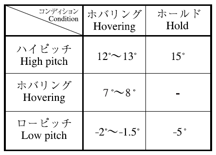
Nachdem die Taumelscheibe und die Heckrotoranlenkung richtig eingestellt waren, fehlten nur noch entsprechende Einstellungen im Kreiselsystem (Flybarless-System) und im Sender. Die Anleitung von ROBAN gibt nur eine konkrete Empfehlung: Der kollektive Blattwinkel sollte zwischen -2/-3° und +9/+10° liegen und linear sein. Das schien mir ein wenig dürftig, also griff ich – mangels eigener Erfahrung – auf die Anleitung für den Dreiblattrotor der HIROBO S-300 zurück. Die folgenden zwei Bilder stammen daher. Nach meinem Verständnis sollte sie auch hier anwendbar sein, weil beide Hubschrauber ein gewölbtes Hauptrotor-Blattprofil haben. Die Anleitung von ROBAN betont, daß die dort angegebenen Blattwinkel auf die gerade Unterseite des Blattprofils bezogen sind. Weil bei diesem Profil mit S-Schlag die Hinterkante höher ist, dürfte die Profilsehne von der Vorderkante zur Hinterkante so gut wie parallel zur Unterseite sein. Deshalb sollten die Winkelangaben von ROBAN und HIROBO vergleichbar sein.
Mit "Hold" ist Autorotation gemeint, also habe ich diesen weiten Bereich
von -5° bis +15° als absolute Grenzen im Microbeast Flybarless-System
eingestellt (was dann -100% bis +100% im Sender sind). Die langen Servoarme
würden noch größere (übermäßige) Ausschläge
erlauben.
Das mag jetzt immer noch übermäßig erscheinen, aber im Notfall (Heckrotorausfall) könnte es nötig sein. Wenn ein zyklischer Blattwinkel zu einem schon großen kollektiven hinzukommen muss, dann sollte das Kreiselsystem beim Mischen von beiden diese absoluten Grenzen einhalten.
Die 15° Blattwinkel machen mir keine Sorgen, weil gewölbte Profile höhere Anstellwinkel erreichen als symmetrische und am Drehflügel noch höhere – und weil der Anstellwinkel wegen des Rotorabwinds deutlich kleiner ist als der Blattwinkel.
Die Anleitung von ROBAN erwähnt, daß schwere Scale-Hubschrauber (wie dieser) sehr schwer in Autorotation sicher zu landen sind, besonders aus dem Schwebeflug. Wir werden das also nicht unnötig tun, müssen es aber, wenn der Heckrotor ausfällt. (Hoffentlich nicht, aber trotzdem übe ich im Simulator.) Meine Multiplex-Sender haben alle schon einen besonderen, vorrangigen Flugmodus für Autorotation, in dem der maximale (100%) positive und negative Blattwinkel möglich ist. In allen anderen Flugphasen (wie Multiplex das nennt) ist der Blattwinkel von vorneherein etwas begrenzt.
In meinem neuen Sender PowerBox ATOM ist nichts dergleichen vorbereitet, also habe ich es dort anhand der Tabelle oben und der Diagramme unten (beide von HIROBO) nachvollzogen. Nach der Spalte "Hovering" in der Tabelle soll der Blattwinkel zwischen -2° bis -1.5° und +12° bis +13° liegen, und nach dem linken Diagramm soll die Pitch-Kurve aus zwei Geradenstücken bestehen. Das bedeutet (1) der Pitch-Knüppel ist beim Schwebeflug ungefähr in der Mitte, (2) die Pitch-Kurve ist in dem Bereich relativ flach und lässt feinfühliges Steuern zu, und (3) wir nehmen für kleine Blattwinkel eine steile Kurve in Kauf, brauchen sie aber nur am Boden. Weil der ATOM keine speziellen Hubschrauber-Kurven hat, nur allgemein Kurven für Knüppelausschläge, müsste die schwarze Skalierung der Diagramme eigentlich -100/0/+100 (statt 0/50/100) sein.
Die rote Blattwinkel-Skalierung zwischen den beiden Diagrammen habe ich hinzugefügt, ebenso wie im linken Diagramm die von mir wirklich eingestellte (rote) 5-Punkt-Kurve (-2°|+4°|+7°|+10°|+13°) für meine drei "normalen" Flugphasen und die (blaue) ROBAN-Gerade zum Vergleich. Meine rote Kurve ist ein wenig steiler als die schwarze von HIROBO, um mehr maximalen Blattwinkel für den Notfall zu haben (den Wirbelringzustand, der dann auch bald kam). Sie entspricht aber der Tabelle und ist nicht steiler als die von ROBAN vorgeschlagene (blaue) Gerade (-2°|+1°|+4°|+7°|+10°), die ebenfalls eine Steigung von 3° pro Viertel Knüppelausschlag hat. Dort ist man im Schwebeflug (+7°) aber schon bei Dreiviertel Knüppelausschlag und kommt nur bis maximal 10° – beides gefällt mir nicht. Jedenfalls ist in "normalen" Flugphasen die Steigung pro Viertel Knüppelausschlag (3°) nur 60% von der in der Flugphase Autorotation (5°) – eine Art Dual Rate.
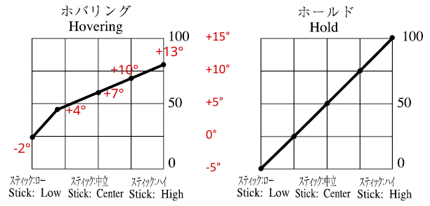
Diese Pitch-Kurven für "normale" Flugphasen (links) und
für Autorotation (rechts) sind so verschieden, daß ein weicher,
langsamer Übergang (vielleicht 1 oder 2 Sekunden)
eingestellt werden sollte.
Es gibt keine Empfehlungen für die Heckrotor-Blattwinkel, weder von ROBAN noch von HIROBO. I habe die Anlenkung so eingestellt, daß bei Servo in Mittelstellung der rechtwinklige Umlenkhebel im Heck sowohl zum Heckrohr als auch zur Heckrotorwelle parallel ist. Das ergibt ungefähr 6° "Mittel"-Blattwinkel. Dann habe ich einfach +/-9° nach jeder Seite im Microbest Kreiselsystem eingestellt. Die Kreiselempfindlichkeit für das Heck wurde auf den empfohlenen Standardwert eingestellt, was genau gepasst hat. In der Flugphase Autorotation wird der "Mittel"-Blattwinkel vom Kreiselsystem automatisch – wie von ROBAN empfohlen – auf 0° gestellt.
Die Blattwinkel an Haupt- und Heckrotor bei verschiedenen Drehzahlen wurden im Simulator überprüft. Wenn jemand ein schwereres Modell oder einen anderen Motor hat oder mit anderen Drehzahlen fliegt, könnte er das durchaus auch tun (siehe unten). Jedenfalls stellte sich heraus, daß bei 1100 U/min Hauptrotordrehzahl der Blattwinkel im Schwebeflug (ohne Bodeneffekt) 6,5° beträgt – sogar 1° weniger als von HIROBO empfohlen. Bei nur 1000 U/min ist der Blattwinkel 7,6°, also ist diese Drehzahl immer noch kein Problem. In beiden Fällen ist der Blattwinkel am Heckrotor ungefähr 11°, während er am Boden nur ungefähr 6° beträgt (mechanisch eingestellte Neutralstellung). Als Fluggewicht wurde 9 kg angenommen.
Im Sender sind drei kombinierte Ausschlagraten (100%, 80% und 60%) und Expo-Werte (50%, 40% und 30%) an einem Dreifachschalter eingerichtet. Sie sind unabhängig von den Flugphasen und gelten für zyklischen Blattwinkel und Heckrotor-Blattwinkel. Die Kombinationen ergeben ungefähr die gleiche Expo-Kurve um die Knüppel-Mitte herum, also unabhägig von der Rate. Eigentlich benutze ich nur die kleinste Rate.
Die Anleitung von ROBAN betont, daß Scale-Hubschrauber große Massenträgheit besitzen und deshalb im Flybarless-System eine geringere Kreiselempfindlichkeit eingestellt werden muß als für 3D-Hubschrauber. Das erreicht man mit einer speziellen Einstellung im Microbeast Kreiselsystem, die für einen ausgewählten "Charakter" des Helis (hier "scale" oder ähnliches) einige Parameter automatisch einstellt.
Drei "normale" Flugphasen (nicht Autorotation) sind eingerichtet, um im Flug zwischen verschiedenen Hauptrotordrehzahlen umzuschalten: 1040 U/min (sparsam), 1100 U/min (normal) und 1160 U/min (böiger Wind). Dafür wurden diagonale "Gaskurven" mit 33 Punkten verwendet, die oben auf die jeweilige Solldrehzahl begrenzt sind (die der Governor dann umsetzt). Der "Gas"-Kanal ist einem Drehknopf am Sender zugeordnet, so daß ich immer noch von Hand einen langsamen Hochlauf steuern kann (ungefähr wie mit einem Limiter in früheren Sendern). Sonst wird der Übergang von einer Drehzahl zur anderen vom Sender verlangsamt (Übergangszeit zwischen Flugphasen) als auch vom Regler (langsamer Hochlauf).
Die Flugphase Autorotation könnte eigentlich die Soll-Rotordrehzahl ("Gaskurve") ganz auf Null heruntersetzen, aber sie wird (nach der Anleitung zum Regler von YGE) nur auf etwas unter 20% des Maximalwertes gesetzt. Das soll einen unmittelbaren Wiederhochlauf des Motors ermöglichen, wenn man zum Testen oder Üben die Autorotation eingeschaltet hat und sie wieder beenden will. Der Regler (Governor) geht nämlich in den langsamen Hochlauf, wenn Null gesetzt wurde, und das würde zu lange dauern. Andererseits könnte ein schneller Hochlauf von weniger als 10% bis 20% der Maximaldrehzahl den Motor überlasten.
Fliegen
Das folgende Bild zeigt den Hubschrauber nach dem Erstflug am 29. September 2024. Die Heckrotorblätter stehen hier in die falsche Richtung gedreht, weil das Kreiselsystem reagiert hat, als ich den Heli beim Tragen gedreht habe. Der Schatten auf dem Heck stammt von unserer Birke und zeigt wieder, daß die rote Farbe in Sonnenlicht viel heller aussieht als sonst. Man sieht auch, daß im Innenraum des Helis alles "scale" ist. Bei den 700 und 800 Modellen von ROBAN ist dort eben keine Mechanik wie bei den kleineren 600ern. Umso mehr wird zumindest eine Pilotenpuppe gebraucht (und später wurde eine hinzugefügt). Das Geräusch des Helis gefällt mir gut, ein Soundmodul brauche ich nicht.

Ein oder zwei Hauptrotorblätter liefen noch nicht in der Spur, aber das wurde vor dem zweiten Flug behoben. Sonst gab es nichts zu bemängeln, außer vielleicht, daß beim Hochlauf zeitweise die Höhenleitwerke in Resonanz mit irgendwelchen Schwingungen kamen und auf und ab vibrierten. Eine nachträgliche Abhilfe ist schwer vorstellbar (vielleicht dünne Verspannungen).
Der Heli fliegt sehr ruhig und stabil, aber auch sehr agil. Das Flybarless-System (Microbeast) ist ganz nach den Empfehlungen des Herstellers eingestellt und die passen offensichtlich hervorragend. Dazu gehört, die maximal möglichen Taumelscheibenausschläge anzugeben. (Deshalb wurden noch die Servoarme gewechselt.) Diese Ausschläge sind im normalen Betrieb bei weitem übertrieben. Am Sender sind drei Möglichkeiten mit 100%, 80% und 60% Rate sowie 50%, 40% und 30% Expo per Schalter wählbar. Ich fliege bisher nur mit der kleinsten Rate und werde wohl noch geringere ausprobieren (und mehr Expo). All das gilt auch für den Heckrotor.
Nur sollte man vor dem Fliegen etwas beachten: Das Microbeast Flybarless-System braucht unmittelbar nach dem Einschalten absolute Ruhe, das heißt nicht die kleinste Erschütterung. Der Heli sollte möglichst waagerecht stehen. Erst wenn dann nach einer Weile die Taumelscheibe auf und ab bewegt wird, hat das System sich kalibriert und der virtuelle Horizont stimmt. Und nachdem der Heli zum Startpunkt getragen und dort abgestellt wurde, stelle ich noch die Heckrotorblätter in Normalstellung (ungefähr 6°). Dann gelingt der Start ohne Kippeln und Wackeln. (Vermutlich ist das bei allen Flybarless-Systemen so, aber ich habe nur zwei Microbeasts.)
Der Schwerpunkt des Helis liegt ein ganzes Stück vor der Rotorwelle. Offensichtlich gleicht das Kreiselsystem das "stillschweigend" aus, das heißt es hält den Heli automatisch waagerecht. (Gut daß der Hauptrotor vier Blätter hat und nicht nur zwei.) Also werde ich wohl keinen Ballast ins Heck tun, auch nicht, wenn Pilotenpuppen vorne hineinkommen.
Die Flugleistung des 8,8 kg schweren Helis (7 kg ohne Akkus) reicht für "Scale" sicher aus – der 700er Motor an 12s 5000 mAh LiPo, die 1100 U/min des 1,60m-Hauptrotors, die vier Blätter mit S-Schlag-Profil. Und die Leistung des Heckrotors reicht sicher aus, den Heli in Seitenwind auf der Stelle zu halten und um seitwärts zu fliegen. (Und die Leistung reicht immer noch sicher aus bei nur 1040 U/min des Hauptrotors.) Das folgende Video zeigt die ersten zwei Minuten des zweiten Fluges am 6. Oktober 2024 und mehr meine "eckige" Flugweise als das Verhalten des Helis. An die Steigleistung und die Agilität dieses Hubschraubers muß ich mich erst noch gewöhnen (und auch noch an meinen neuen Sender).
Die aufgezeichneten Telemetriedaten zeigen, daß – im Durchschnit – im Schwebeflug etwas mehr als 25 A Strom gezogen werden, im Rundflug etwas mehr als 20 A. Im Durchschnitt wird hier betont, weil der Strom stark schwankt – zwischen 10 A und 40 A. Nur in heftigen Flugbewegungen steigt er über 40 A und nur einmal (als ich in Panik voll Pitch gegeben habe) gab es eine Spitze von 87 A. (Das kann durch Begrenzung des Kollektiv-Pitch-Ausschlags im Sender verhindert werden.) Der mit 135 A belastbare Regler (YGE) ist also für normalen Flug überdimensioniert. Er wird aber trotz oder wegen dieser niedrigen Teillast (15% bis 20% vom Grenzwert) nur bis zu 50°C warm (wahrscheinlich durch den "aktiven Freilauf").
Der Verbrauch beträgt durchschnittlich ungefähr 360 mAh/min (entspricht 21,6 A). Nach 7 Minuten Flugzeit (einschließlich Hochlauf) beträgt die Zellenspannung der beiden 6s-Akkus (5000 mAh) noch 3,8 V (Lagerspannung). Die beiden 2s-"Empfängerakkus" (2200 mAh) verlieren bis zu 0,1 V Zellenspannung pro Flug, also sind sie gut für drei oder vier solche Flüge. Ohne Gefahr für alle Akkus könnte man Flüge zu je 8 Minuten Dauer machen, mit den "Empfängerakkus" vier hintereinander, müsste sie am Ende aber wieder auf Lagerspannung aufladen.
Der Verbrauch beträgt nur 325 mAh/min (entspricht 19,6 A) bei nur 1040 U/min Hauptrotordrehzahl – ohne irgendeinen merklichen Verlust an Leistung und Agilität. Eine noch kleinere Hauptrotordrehzahl (und weniger Strom) ist möglich. Man könnte Flüge zu je 8 Minuten Dauer machen, mit den "Empfängerakkus" jetzt aber nur drei hintereinander, und hätte am Ende immer noch ungefähr Lagerspannung.
Übrigens kann man jetzt den durchschnittlichen Servostrom schätzen. Vier 7-Minuten-Flüge machen ungefähr eine halbe Stunde, 3,8 V Leerlaufzellenspannung bedeutet – sehr grob gerechnet – halbe Entladung der beiden parallelen 2200 mAh "Empfängerakkus". Diese sind also mit 1C Strom belastet, das sind 4,4 A. Großzügig aufgerundet sind das 5 A als Größenordnung (genauer gerechnet sogar 5,4 A, und immer noch knapp 5 A mit 15mm-Armen an den Taumelscheibenservos). Der Servostrom ist im Schwebeflug deutlich geringer als im Rundflug (siehe geringeren Spannungsabfall am Ende des Beispieldiagramms unten).
Der Hubschrauber fliegt sich sehr angenehm, aber es gibt ein paar Dinge zu beachten: Ich bin noch in der Lern- und Gewöhnungsphase und in einem Fall bekam ich einen Schrecken, als der Heli im Schwebeflug plötzlich durchsackte. Voller Pitch-Ausschlag ließ ihn zwar wieder hochschießen, aber ich fühlte mich an einen Rat aus der Anleitung erinnert – den Heli immer in Bewegung zu halten, außer in Bodennähe (im Bodeneffekt). Es könnte eine Neigung zum Wirbelringzustand geben.
Und ich mag die Form, das Farbschema und die Farbe des Hubschraubers sehr, aber gerade die können schlechte Sichtbarkeit verursachen. Das Farbschema hat überhaupt keine klaren geraden Linien und nicht einmal die Landekufen sind parallel. Bei bedecktem Himmel sieht der Rumpf dunkel aus, der Kontrast ist gering. Die abgerundete Form wiederum hat einen Umriss, der es manchmal schwer macht, die Fluglage des Helis zu erkennen und die Orientierung zu behalten. Jedenfalls fliege ich den Heli bei Sonnenschein entspannter als bei Bewölkung. Dieser Heli ist sehr schön, aber nichts für Anfänger. Man kann nicht alles haben.
Zum Schluß zwei Kommentare: Einer auf YouTube nennt den Heli eine Schönheit – einverstanden. Der Enkel eines Vereinskollegen nennt ihn einen Weihnachtshubschrauber – nicht einverstanden, aber verstanden (und unwissentlich liegt er nicht ganz falsch, siehe oben).
Fazit
… im Telegrammstil:
- Schönes, vorbildgetreues Modell.
- Unwesentliche Details sind nicht "scale".
- Diese können beim Bau (aber nicht danach) korrigiert werden.
- Solide aufgebaut, gute Qualität, guter Preis.
- Gut gestaltete Mechanik.
- Heckrotor kann auf rechtsdrehend geändert werden.
- Bei Autorotation dreht der Heckrotor mit.
- Fliegt ruhig aber ist doch agil.
- Nicht für Anfänger – Erfahrung hilft.
- Aber auch nicht besonders schwierig.
Für – auch einige schwierige – Details siehe vorherige Abschnitte.
Die wichtigsten Informationen sind in den folgenden Anmerkungen zusammengefasst, wichtige Details siehe oben.
Anmerkungen
Ein Motor der Größe 700 mit kv 450 ist gerade richtig für diesen Heli. Ein größerer Motor (750 oder 800) hätte nur eine übermäßige Leistungsreserve, einer mit mehr kv (520 oder 560) würde mehr Strom ziehen und sogar den Regler belasten. Nur wenn man billige Komponenten (Motor, Regler, Akku) mit hohem Innenwiderstand verwendet, sollte es eher ein Motor der Größe 750 sein, um eine gute Leistungsreserve zu haben.
Der Motor sollte nicht viel mehr als 50 mm Außendurchmesser haben (wahrscheinlich höchstens ungefähr 60 mm) um in die Ausbuchtung im Rahmen zu passen. Es muß in jedem Fall eine Ausführung mit langem Wellenstummel sein: 38,5 mm oder nur etwas länger (und 6 mm Durchmesser).
Ein Regler, der mindestens 100 A Strom verträgt, ist auf der sicheren Seite. Er sollte aber in jedem Fall teillastfest sein ("aktiver Freilauf").
Zwei 6s LiPo-Akkus mit 5000 mAh Kapazität genügen dann für 8 Minuten Flugzeit (solange sie neu sind), kleinere Akkus (4000 mAh) sind also möglich. Der mittlere Strom ist 20 A bis 22 A; Spitzen gehen bis 40 A, nur in extremen Fällen bis 90 A.
Wegen der recht langen Kabel vom Regler zu den Akkus sind zusätzliche Kondensatoren ratsam. Ein Sicherheitsschalter dürfte dann einen Parallelwiderstand brauchen.
Gute Heli-Servos in Standardgröße (für mindestens 600er Helis) sind nötig. In Hochvolt-Ausführung werden sie aus einem 2s LiPo-Akku gemeinsam mehr als 5 A Strom ziehen (im Durchschnitt). Ein Flybarless-System mit Hochstromanschluß oder eine eigene Servostromversorgung ist ratsam.
13 mm Servohebelarm ist eine Mindestanforderung, sollte aber besser 14 mm lauten. 17 mm Hebelarm funktioniert sehr gut, aber mit 15mm-Armen könnten die Servos 10% weniger Strom ziehen.
Servoarme aus Aluminium sind gut, aber es gibt sie nicht für alle Servo-Marken. Servoarme aus Kunststoff tun es zur Not auch.
Die Längenangabe für die Stoßstangen zur Taumelscheibe ist grundsätzlich richtig, und die mittlere Anlenkstange muß nicht gebogen werden (weil es keine Kollision gibt).
Die beiden Kugellager auf der Welle im Heckrohr ("torque tube") sollten dort ungleichmäßig verteilt sein. Die Gummitüllen außen um die Lager herum müssen richtig mit Schmiermittel in das Heckrohr geschoben werden.
Um den Heckrotor mehr "scale" und aerodynamisch besser
(wirksamer, leiser) zu machen, kann sein Drehsinn umgekehrt werden:
(1) Dazu muss das vordere Winkelgetriebe "umgedreht"
werden.
(2) Beide Kupplungsstücke der Welle zum Heckrotor müssen
mit Schrauben gesichert werden.
(3) Die Blatthalter und Blätter des Heckrotors müssen
ebenfalls umgedreht werden.
Vermutlich sind die Zahnräder wie auch das Schrägkugellager eingestellt und geschmiert und alle Schrauben an den Rotorköpfen sind mit Sicherungslack festgezogen, aber es ist kein Sicherungslack an allen Schrauben in den Carbon-Seitenteilen des Rahmens. Man kann sich jedoch nicht darauf verlassen – also überprüfen!
Das sogenannte EVA-Heckgummi sollte unbedingt auf dem Heckausleger verwendet werden, weil es das Gewicht des Hecks zum großen Teil trägt und damit die sechs kleinen Schrauben entlastet.
Der rechte Pilotensitz und der (zyklische) Steuerknüppel sollten weiter rechts montiert werden, als es durch Schlitze und Bohrung im Kabinenboden vorgesehen ist. Der (kollektive) Pitchhebel sollte links neben dem Pilotensitz sein. Die Sitzfläche sollte tiefer sein.
Die Höhenleitwerke brauchen unbedingt innere Spangen, die auch in der Hecktüte eingeklebt werden müssen und die beide miteinander verbinden!
Die große Heckfinne muß weit nach hinten geneigt sein, viel weiter als mit den Vertiefungen (zum Bohren der Schraubenlöcher) in der Finne und der Hecktüte vorgegeben ist.
An die große Heckfinne gehört noch eine weiße LED als hinteres Positionslicht (nicht im Bausatz enthalten). Der Controller für die Beleuchtung hat schon einen Anschluß dafür.
Mein Exemplar wiegt mit Akkus 8,8 kg (8,0 kg dürfte das absolute Minimum sein). Pilotenpuppe und Ausrüstung kommen hinzu, aber das Gewicht ist noch lange kein Problem beim Fliegen.
Der Schwerpunkt des Modells liegt recht weit vorne, das sollte man beim Zusammenbau bedenken.
Eine Hauptrotordrehzahl von 1100 U/min ist gerade richtig für diesen Heli. Damit ist er agil, aber auch sparsam. Immer noch agil, aber noch sparsamer ist er bei noch kleinerer Hauptrotordrehzahl, zum Beispiel 1040 U/min.
Nach 7 Minuten Flugzeit (einschließlich Hochlauf) bei 1100 U/min Hauptrotordrehzahl haben die (noch recht neuen) 12 5000 mAh LiPo-Zellen noch 3,8 V im Leerlauf (Lagerspannung) – nach 8 Minuten bei 1040 U/min. Ein BEC für die Stromversorgung der Servos würde ungefähr eine ¾ Minute Flugzeit kosten.
Der Maßstab des Modells ist 1:7, also muß das auch der Maßstab einer Pilotenpuppe oder anderen "Zubehörs" sein.
Überlegungen
Einiges lief einfach gut, einiges andere kann – im Nachhinein – als Fehler angesehen werden, besonders im Zusammenhang gesehen. Wenn ich den Hubschrauber noch einmal bauen würde, könnte ich andere Lösungen erwägen.
Die Empfehlung von Scaleflying.de für den Motor war sehr gut. Ein größerer Motor (750 oder sogar 800) hätte nur eine übermäßige Leistungsreserve, würde aber mehr wiegen (80 g oder sogar 125 g) und kosten. Ein Motor mit mehr kv (520) würde (3,2 A) mehr Strom ziehen, was die Flugdauer (um 1 Minute) verringert. Die Anleitung gibt ohnehin nur 5 Minuten Flugzeit an (sogar 3 Minuten weniger), warum auch immer.
Kein Problem, aber auch nicht gut ist, daß der Schwerpunkt zu weit vorn liegt. Je zwei Antriebs- und "Empfänger"-Akkus tragen viel dazu bei, aber sie können nicht weiter nach hinten verschoben werden. Der Regler trägt weniger bei, aber er könnte weiter nach hinten verschoben werden.
In Anbetracht der mehr als ausreichenden Kapazität der Antriebsakkus könnten kleinere und leichtere verwendet werden, zum Beispiel 4000 mAh (anstatt 5000 mAh) mit 20C/40C (anstatt 40C/80C) Strombelastbarkeit. Das würde für diese Anwendung noch ausreichen (1½ Minuten weniger Flugzeit) und einiges an Gewicht (415 g weit vorne) und Kosten sparen.
Ungefähr das Gleiche könnte man mit Antriebsakkus 10s 5000 mAh 20C/40C erreichen, bräuchte dann aber einen Motor mit kv 520 und einen Regler für mindestens 120 A, wie in der Anleitung empfohlen. Geringere Spannung muß schließlich durch höheren Strom ausgeglichen werden.
Mit 12s-Antriebsakkus, gleich welcher Kapazität, könnte der Regler eine Nummer kleiner sein, nur 105 A (statt 135 A). Das spart Gewicht (50 g) und Kosten.
Der Regler könnte weiter hinten montiert werden, nahe beim Motor. Die Kabel zu den Akkus wären noch länger, aber das ist durch die zusätzlichen Kondensatoren schon ausgeglichen.
Der Regler könnte einer mit BEC sein (statt des Opto), was beide "Empfängerakkus" und den Schalter/Mischer ganz einspart (270 g), aber (40 g) mehr wiegt. Ungefähr 250 mAh pro Flug würden zusätzlich aus den Antriebsakkus gezogen (entsprechend einer ¾ Minute weniger Flugzeit), aber das wäre noch kein Problem.
Regler mit BEC scheinen ohnehin gerade üblich zu sein, zumindest wird der hier verwendete Opto aus diesem Grund nicht mehr hergestellt. Und die BECs scheinen heute doch zuverlässig zu sein, anders als noch vor einigen Jahren. Sie können wirklich 12 A Strom liefern, bei wirklich konstanter Spannung, und sie haben sogar eine eingebaute "Weiche" für einen Stützakku, der üblicherweise recht klein (z.B. 2s 450 mAh LiPo) und leicht ist.
Dieser Akku wäre wichtig für mein Sicherheitsgefühl. YGE hat mir jetzt erklärt, wie die Sache funktioniert: Das BEC kann auf nur 7,8 V eingestellt werden, das reicht für die HV-Servos sicher aus. Fällt das BEC aus und der Stützakku springt ein, fällt dessen Spannung schnell unter 7,8 V und das kann von der Telemetrie verkündet werden. Seine Ladung reicht dann für eine sichere Landung immer noch aus. Liegt der Stützakku vor dem Fliegen unter 7,8 V, wird er nach dem Einschalten vom Antriebsakku aufgeladen. Nach dem Fliegen hat er immer noch 7,8 V und damit kann er gelagert werden (vielleicht zur Sicherheit nicht im Heli). Der Stützakku muss also nicht jedesmal vor dem Flug geladen und nachher (auf Lagerspannung) entladen werden – tatsächlich noch einfacher als zwei "Empfängerakkus", die geladen und auf Lagerspannung geflogen werden.
Dann könnte der Stützakku unter der Haube, gleich beim Regler, angebracht werden. Das würde ich aber nur tun, wenn es ein LiFePO4-Akku wäre, weil die nicht brennen. Ihre Zellenspannung liegt zwischen 3,4 V (voll) und 3,2 V (20% geladen, Nennspannung). Ein Akku mit zwei Zellen läge zwischen 6,8 V und 6,4 V, ein wenig höher als ein NiMH-Akku mit 5 Zellen und noch im Spannungsbereich von Hochvolt-Servos (6,0 V bis 8,4 V). Das BEC würde ich dann auf 6,6 V einstellen, damit der Akku zu mindestens 50% geladen ist. Das sind 1,2 V weniger als mit einem LiPo-Akku, aber ein bisschen weniger Servo-Moment und -Geschwindigkeit macht diesem Scale-Hubschrauber nichts aus. (Danke, Cletus, für die Idee.)
BEC-Ausfälle gehen wohl oft auf Spannungs- und Stromspitzen zurück, die von den Servos erzeugt werden. Ein Glättungskondensator in einem Servo-Steckplatz im Flybarless-System oder Empfänger kann davor schützen. Relativ kleine Kondensatoren reichen wohl aus, aber wenn man ("viel hilft viel") große will, sollte man die Pufferkondensatoren nehmen, die eine eigene Elektronik haben. Die laden sich nach dem Einschalten nur langsam auf, mit begrenztem Strom. Einen Pufferkondensator anstatt eines Stützakkus würde ich nicht nehmen, weil mir 50 Sekunden Zeit zum Landen nach einem BEC-Ausfall zu wenig wäre.
Mit BEC wäre der Schalter zum Microbeast HD (Flybarless-System) nützlich. Aber auch das spezielle Adapterkabel vom BEC (im Regler) ist recht dünn und hat am Regler nur einen kleinen "Servostecker", keinen MPX-Stecker – den zu erwartenden Stromspitzen nicht angemessen.
Ein Opto-Regler mit "Empfängerakkus" braucht weder einen Glättungskondensator noch einen Stützakku mit regulierender Elektronik. Das kostet weniger als eine Lösung mit BEC, ist einfacher (dadurch zuverlässiger) und wiegt zumindest nicht viel mehr.
Das sind die zwei oder drei Gründe, weshalb ich immer noch bei der Lösung mit zwei "Empfängerakkus" und einem nicht spannungsregulierenden Schalter/Mischer bleiben würde. Eher könnte ich nur einen (aber größeren) "Empfängerakku" und den Microbeast-Schalter verwenden und ich würde mich immer noch sicherer fühlen als mit BEC. Wenn ich ein Flybarless-System ohne Hochstromanschluß hätte, würde ich sogar eine eigene Servostromversorgung mit Telemetrie verwenden.
Mein Mißtrauen gilt nicht nur dem BEC, sondern auch dem Antriebsakku. Beide sind früher gerne einmal ausgefallen, also zweifaches Risiko. Beides hatte ich selbst schon, aber noch kein Problem mit Empfängerakkus – könnte noch kommen, aber ist sehr unwahrscheinlich. So wird man geprägt…
Man kann auch einfach nur die Kosten senken:
Wenn es noch einen Opto-Regler gibt, dann ist der zusammen mit nur einem "Empfängerakku" und dem Schalter zum Microbeast HD eine immer noch sehr sichere und billige Lösung. Auf Telemetrie im Regler würde ich wegen der Sicherheit nicht verzichten, muss man heute aber auch nicht mehr.
Motor, Regler und Akkus müssen nicht die hier gewählten Premium-Produkte sein. Es gibt jeweils deutlich billigere von anderen Herstellern, immer noch in guter Qualität. Möglicherweise haben sie aber zusammen so viel höheren Innenwiderstand (und der Motor Leerlaufstrom), daß die Motorgröße 750 angebracht ist (wegen der Leistungsreserve, siehe unten), die auch in der Anleitung empfohlen wird.
Den Sicherheitsschalter für die Antriebsakkus kann man auch mit einem einfachen Stiftschalter betätigen, der ist billiger als der Empfänger-Adapter. Man kann den Sicherheitsschalter auch ganz weglassen, wenn man erst am Startplatz die Akkus anschließt oder die Abschaltung durch den Regler sicher genug ist. Dann sollte man aber Blitzschutz in den XT90-Steckern haben.
Das Microbeast HD Flybarless-System genügt mit der normalen Firmware-Version. Die ProEdition bringt die Rettungsfunktion, aber die wird für diesen Scale-Heli nicht gebraucht. Auch die Governor-Funktion wird hier nicht gebraucht, die im Regler ist gut genug. Auf den Hochstromstecker und den Schalter, das heißt die HD-Version, würde ich nicht verzichten.
Die Servos werden nämlich viel Strom ziehen. Deshalb würde ich immer Hochvolt-Servos wählen, und um einen 2s LiPo "Empfängerakku" ohne Spannungsregler verwenden zu können. Metallgetriebe muss sein, coreless und brushless nicht. Viel kann man damit heute aber nicht mehr sparen. Eher sucht man nach einem günstigen Angebot für "normale" Servos, die hier ja keine 3D-Leistung erbringen müssen.
Schließlich noch etwas für Perfektionisten:
Alle Schrauben im Bausatz scheinen spröde und leicht abzuscheren. Das vermeidet man natürlich, indem man sie vorsichtig und nicht zu fest anzieht. Aber man könnte sie auch durch zähere ersetzen, wenngleich das ein ziemliches Projekt wäre, weil es viele verschiedene sind. Wer aber eine gute Quelle hat, könnte sich daranwagen.
Alle Kugelgelenke bestehen aus einem recht harten Kunststoff und haben ein klein wenig Spiel. Man findet aber leicht Anbieter von spielfreien Gelenken aus zähem Kunststoff, auch in den passenden Abmessungen.
Weiteres
Artikel über die Bell 429 auf Wikipedia
Fotos von den Bell 429 der Air Zermatt auf airliners.net
Webseite von Bell zu ihrer 429
Webseiten von ROBAN MODEL in China (Englisch)
Webseiten von Scaleflying.de
Webseite von Scaleflying.de zur ROBAN Bell 429 Air Zermatt
Webseite von Scaleflying.de zur ROBAN Bell 429 Air Zermatt im Web Archive
YouTube-Kanal von Scaleflying.de
Webseite von KONTRONIK zum Motor Pyro 700-45
alte Webseite von KONTRONIK zum Motor Pyro 700-45 im Web Archive
Webseite von YGE zu deren Hochvolt-Reglern, besonders Opto 135
BEASTX Microbeast Plus Wiki-Seite
Baustufenfotos zur ROBAN Bell 429 auf helipoint.at
Baubericht zur ROBAN Bell 429 auf rc-heli.de
noch ein Baubericht zur ROBAN Bell 429 auf rc-heli.de
Baubericht zur ROBAN Bell 429 auf vstabi.info (Mikado-Forum)
Baubericht zur ROBAN Bell 429 auf RCGroups.com (Englisch)
noch ein Baubericht zur ROBAN Bell 429 auf RCGroups.com (Englisch)
Bericht von John Salt zur ROBAN AS350 (Englisch)
meine Playlist auf YouTube mit Videos von der ROBAN Bell 429
meine Playlist auf YouTube mit Videos von meiner ROBAN Bell 429
Telemetrie
Dieser Modellhubschrauber ist, wie meine HIROBO Schweizer 300, mit einem modernen Elektroantrieb mit Drehzahlregler (governor) ausgerüstet. Deshalb muß man auch ihn mit Telemetrie betreiben, um die Flugsicherheit zu gewährleisten.
Empfänger und Regler liefern schon die Hälfte der gewünschten Werte; nur für eine bessere Spannungsüberwachung der beiden Antriebsakkus wurden zwei zusätzliche Sensoren vorgesehen, die sich aber dann als hier nicht verwendbar herausstellten. Für die spätere Interpretation dieser Daten fügt ein GPS 3D-Positionsdaten hinzu. Der FlightRecorder zeichnet alle Telemetriedaten auf, um sie später – regelmäßig oder möglicherweise auch nach einem Unfall – auswerten zu können.
Die meisten Werte werden nicht nur aufgezeichnet und übertragen, sondern auch auf Einhaltung einstellbarer Grenzen überwacht. Werte und eventuelle "Alarme" werden im Senderdisplay angezeigt und von der Sprachausgabe angesagt. Das muß sinnvoll konfiguriert werden, wozu ich mir einen zusammenhängenden Plan in Form einer Kalkulationstabelle anfertige.
Sensoreinstellungen
Mein Sender Cockpit SX 12 (gekauft 2020) hat ein Betriebssystem ähnlich wie in einem Smartphone und einen Touch Screen. In der Anzeige der Telemetriewerte läßt sich die Schriftgröße und damit die Zahl der angezeigten Werte verstellen. Für mich sind sechs Zeilen der beste Kompromiß zwischen Übersicht und Lesbarkeit. So habe ich das Display durch Ziehen mit dem Stift eingestellt. Hier in der Planungstabelle sind zwei Seiten mit sechs Zeilen durch rote Linien abgegrenzt, so daß eine mit vier Zeilen übrig bleibt:
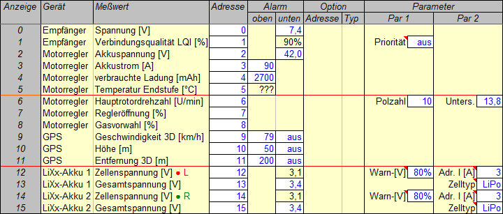
Das sind die Grundeinstellungen der Telemetriegeräte. Bis zu 16 Werte können auf dem MSB übertragen werden; die Anzeigereihenfolge (linke Spalte) ergibt sich aus den gewählten Busadressen (vierte Spalte).
Alarm meint einstellbare Ober- und Untergrenzen, Parameter sind in den jeweiligen Geräten zusätzlich einzustellen. (Optionen – das sind Maximal-, Minimal- oder Mittelwerte – werden hier nicht gebraucht, weil alle Telemetriedaten aufgezeichnet werden.)
Hier werden alle 16 möglichen Werte benutzt, aber eine besondere Anordnung auf Seiten wurde nicht versucht. Die Werte der fünf Geräte am Sensorbus wurden einfach hintereinander aufgereiht. Trotzdem ergibt sich eine recht sinnvolle Aufteilung: Der ersten Seite mit Werten, die während des Fluges interessant sind, folgt eine zweite mit Werten, die später analysiert werden, und eine dritte mit den Spannungen der Antriebsakkus.
Die beiden Werte des Empfängers wurden auf den voreingestellten Plätzen 0 und 1 gelassen. Deshalb funktioniert die Warn-LED des Senders für zu geringe Empfängerspannung. Für einen 2s LiPo Empfängerakku sind 7,4 V unter Last eine sichere Warnschwelle, weil sie genug Restladung zum Landen bedeutet, selbst wenn einer der beiden Akkus ausgefallen ist. "Priorität aus" heißt, daß kein Wert (keine Adresse) häufiger übertragen wird als die anderen – das braucht man eigentlich nur für einen hochauflösenden Variometerton.
Der Regler liefert sieben Werte – alle interessant. "Regleröffnung" und "Gasvorwahl" sind für mich neu und besonders interessant. Die Reihenfolge wurde nur insofern verändert, als die "verbrauchte Ladung" auf Platz 4 vorgezogen wurde, damit im Sender die Warn-LED für zu geringe Akkuladung funktioniert. Die "Hauptrotordrehzahl" wurde dafür auf Platz 6 gesetzt. Polzahl des Motors und Getriebeuntersetzung muß man angeben, weil damit die Rotordrehzahl aus der Feldfrequenz des Motors berechnet wird.
Die im Regler gemessene "Akkuspannung" ist eigentlich überflüssig, weil sie nur etwas geringer sein wird als die direkt an den Akkus gemessene Spannung (wegen der Widerstände dazwischen). Trotzdem ist die Unterspannungswarnung aktiviert – als Ersatzlösung. Die Warnschwelle ist auf 42,0 V Gesamtspannung gesetzt, entsprechend und als Ersatz für 3,5 V pro Zelle – den eigentlich gewünschten Wert, der aber mit den Spannungssensoren nicht möglich ist.
Für den "Akkustrom" ist eine Warnschwelle von 90 A eingestellt – weit mehr als die höchstens erwarteten 40 A, weit weniger als die 135 A Belastbarkeit des Reglers und 200 A der (40C) Akkus, aber ungefähr was der Motor kurzzeitig verträgt.
Die beiden Akkus – je 6s 5000mAh 40/80C LiPo – werden nur bis 4,18 V (statt 4,20 V) pro Zelle aufgeladen, deshalb ist die Kapazität nur 4850 mAh (97% der Nennkapazität). 20% werden abgezogen, um die Abnutzung durch Gebrauch und Alter vorwegzunehmen, also bleiben noch 3880 mAh. Bei 30% Restladung, das sind 1200 mAh, soll gewarnt werden. Der Regler zählt einfach die "verbrauchte Ladung", also muß die Warnschwelle auf 2680 mAh oder gerundet 2700 mAh eingestellt sein.
Die 3D-Positionsdaten des GPS werden in jedem Fall vom FlightRecorder aufgezeichnet. Damit kann in Google Earth der Flugweg dargestellt werden. In Diagrammen sind aber auch "Geschwindigkeit 3D", "Höhe" und vielleicht "Entfernung 3D" nützlich. Diese müssen während des Fluges angezeigt (auf dem MSB gesendet) werden, damit der FlightRecorder sie aufzeichnen kann. Alle drei oberen Warnschwellen sind aktiviert. Das GPS ist auf "langsames Flugzeug" eingestellt, das heißt horizontale Geschwindigkeit bis zu 79 km/h und vertikale bis zu 54 km/h. Die Warnschwelle für "Geschwindigkeit 3D" wurde einfach auf 79 km/h eingestellt. Eine Warnung vor zu großer "Höhe" erfolgt bei 50 m, unserer Mindest-Obergrenze bei aktiver Kontrollzone und meiner persönlichen Grenze, um nicht die Orientierung zu verlieren. Aus diesem Grund wird auch bei meiner persönlichen Grenze von 200 m "Entfernung 3D" gewarnt.
Die beiden speziellen Spannungssensoren prüfen nach dem Anstecken an den jeweiligen Antriebsakku die Spannung der einzelnen Zellen und zeigen auf dem Platz der Zellenspannung den Ladezustand (in %) des Akkus. Wenn eine Zellenspannung unter dem für "LiPo" üblichen Wert für "80%" Ladung liegt, wird eine Warnung ausgegeben – ein Sicherheitsmerkmal. Die Gesamtspannung sagt nicht viel aus, aber es wird empfohlen sie anzuzeigen. Wenn die hier eingestellte Schwelle von 3,4 V Zellenspannung unterschritten wird, erscheint der Alarm dann auf dem Platz der Gesamtspannung. Nur die sogenannte absolute Unterspannungswarnung (3,1 V für LiPo vorgegeben) erscheint dann auf dem Platz der Zellenspannung. Der voreingestellte Wert von 3,4 V hat sich bei mir bewährt – er ist nicht zu hoch. Er sollte sogar auf 3,5 V erhöht werden, damit früher gewarnt wird (bei 25% Restladung statt bei 15%), aber das erlauben die Sensoren leider nicht. Sie sind aber nützlich als weitere Warnstufe, weil sie eine zu geringe einzelne Zellenspannung erkennen. Wenn die Sensoren die Adresse des Stromes ("3") kennen, geben sie bei kurzen Stromspitzen keine Unterspannungswarnung aus.
Schutzkonzept
Die Warnschwellen wurden so gewählt, daß der Hubschrauber möglichst sicher ist, aber auch die Antriebsakkus geschont werden:
Unter normalen Umständen kommt zuerst vom Regler die Entladungswarnung bei 30% (Nenn-)Restladung eines gealterten Akkus (1200 mAh nach 2700 mAh Entladung, das heißt bei 43% Restladung eines neuen Akkus).
Bei ungefähr 25% (wirklicher) Restladung wird dann die Schwelle von 42,0 V Akkuspannung – entsprechend 3,5 V pro Zelle – unterschritten. Wenn schon nicht nach der ersten, sollte man nach dieser zweiten Warnung landen.
Denn wenn erst die Spannungssensoren bei 3,4 V Zellenspannung (oder 40,8 V Akkuspannung) warnen, ist die Restladung nur noch ungefähr 15%. Das ist den Akkus schon abträglich, aber immer noch genug für eine sichere Landung, bevor der Regler die Leistung so reduziert, daß die Zellenspannung wenigstens nicht unter 3,3 V sinkt, um einen sofortigen Akkuschaden zu verhindern (oder, ohne diese Reglerfunktion, bevor der Akku zu weit entladen ist).
Die Entladungswarnung ist also der eigentliche Hinweis, bald zu landen – wie eine weiße Leuchte im Cockpit. 42,0 V Akkuspannung (entsprechend 3,5 V Zellenspannung) ist eine dringende Warnung, umgehend zu landen (ASAP, so bald wie möglich) – wie eine gelbe Leuchte. 3,4 V Zellenspannung (entsprechend 40,8 V Akkuspannung) ist die Aufforderung, sofort zu landen – wie eine rote Leuchte. Danach würde man zumindest zum Teil die Kontrolle verlieren, weil irgendwann die Leistung zum Fliegen nicht mehr ausreicht.
Die Umstände sind nicht normal, wenn die Akkus kalt oder alt sind. Dann haben sie nicht (mehr) die Nennkapazität und die Spannungswarnungen kommen bald nach der Entladungswarnung, im Extremfall sogar früher. Darauf kann man sich hier verlassen, denn ein Hubschrauber zieht – anders als ein Flugzeug – ständig viel Strom.
Im Falle einer schlechten Zelle können die Spannungssensoren gerade noch rechtzeitig warnen, womöglich ohne daß vorher andere Warnungen gekommen sind. Man muß also immer gut auf die Art einer Warnung achten – die rote Leuchte kann unvermittelt aufleuchten.
Die Uhr im Sender, welche die Motorlaufzeit zählt, ist zur Schonung der Antriebsakkus auf 7 oder 8 Minuten eingestellt, je nach Rotordrehzahl (1100 beziehungsweise 1040 U/min). Neue Akkus haben nach dem Flug noch 3.8 V Zellenspannung (Lagerspannung), also 50% Ladung, gealterte nur noch 30%. Dann kommt auch die Entladungswarnung, aber sonst werden Warnungen oder Alarme nur ausgelöst, wenn wirklich etwas faul ist.
(Die Gründe für dieses Schutzkonzept sind hier erläutert.)
Sprachausgabe
Mein Sender Cockpit SX 12 (gekauft 2020) hat eingebaute Sprachausgabe, die sich konfigurieren lässt, aber einfacher als der Souffleur, der mit dem alten Sender ROYALpro9 (gekauft 2008) verwendet wurde. Mit etwas Mühe kann man zwar spezielle Ansagen für Sensorwerte in den Sender bringen, aber die sind dann an feste Adressen gebunden. Man müsste also in allen Modellen jeweils dieselben Adressen (z.B. für Rotordrehzahl) verwenden. Das ist praktisch unmöglich, also bleibt es bei den Standardansagen (z.B. “Sensor 3”). Die sind wiederum nutzlos, weshalb ich sie alle durch einen kurzen Hinweiston ersetzt habe, um die Ansagezeit zu verkürzen. Man kann alle Ansagen immer noch an ihrer Einheit erkennen, notfalls auch am Wert, und kurze Ansagen sind in jedem Fall gut.
Man kann nur eine Gruppe von Werten bilden, die gemeinsam angesagt werden. Aber man kann nicht nur Schalter verwenden, um die Ansage auszulösen, sondern auch Neigungen oder Bewegungen des Senders. So lasse ich mir nur wenige kritische Werte ansagen: den Strom, die verbrauchte Ladung, die Reglertemperatur und die kleinsten Zellenspannungen. Getrennt davon kann auch die verbleibende Flugzeit angesagt werden – durch Kippen des Senders.
Übrigens kann man Sprachausgabe auch an Schalterstellungen binden. Das kommt mir sehr entgegen, denn ich vergesse gerne, welcher Schalter und welche Schalterstellung für was gilt. Jetzt kann ich es einfach ausprobieren und es wird mir angesagt. Natürlich mache ich das nur, bevor der Hubschrauber aktiviert wird; dann kann ich es mir während der nächsten Flüge wieder merken.
Neuer Sender
Mein neuester Sender, PowerBox ATOM M-Link (erworben im Juli 2024), ist besonders gut in Telemetrie und Sprachausgabe. Alarmauslösende Grenzwerte müssen nicht mehr in den Sensoren eingestellt werden. Statt dessen gibt es bis zu vier Grenzwerte (zwei Ober- und zwei Untergrenzen) pro angezeigtem Wert im Sender. Sie können also jederzeit leicht geändert werden. Die Art des Alarms ist weitgehend konfigurierbar, von Pieptönen über Vibration bis zur Sprachausgabe. Letztere braucht keine vorbereiteten Klangdateien, weil es sich um ein vollwertiges Text-zu-Sprache-System handelt. Sprachausgaben sind also sehr leicht einzurichten. Natürlich kann man Sprachausgabe auch an Schalterstellungen binden. Das ganze Telemetriekonzept wurde in diesem Sender eingerichtet, besonders das Schutzkonzept.
Der Sender zeichnet automatisch alle Telemetriedaten auf, so daß der FlightRecorder im Modell eigentlich überflüssig ist. Aber die Daten mit einem USB-Stick auf einen PC zu übertragen ist genauso umständlich wie die MicroSD-Karte aus dem Modell zu nehmen und am PC einzulesen. Außerdem mag ich die Art der Diagramme in der PowerBox Terminal App nicht. Also werde ich bei dem bleiben, was ich habe – FlightRecorder und LogView.
Obwohl sie nicht zur Telemetrie zählt, soll eine weitere gute Funktion hier erwähnt werden: eine Art Vorflug-Checkliste. Das heißt der Sender startet nur, wenn vorher definierte Bedingungen erfüllt sind, zum Beispiel Hauptschalter aus, Pitchknüppel in einer bestimmten Stellung, und so weiter.
Problem
Ähnlich wie ich den Parallelwiderstand für den Sicherheitsschalter "vergessen" hatte, so bin ich auch erst nachträglich darauf gekommen, daß die zwei Spannungssensoren nicht funktionieren können. (Steht schon seit Jahren im Multiplex-Forum zu lesen, aber kein Wort darüber in der Anleitung.)
Es fehlt eine Masseverbindung zwischen Sensorbus (Empfänger) und Antriebsakku (wegen Regler ohne BEC, mit Optokoppler), weil der Sensor nicht "potentialfrei" arbeiten kann (was ich aber fälschlicherweise angenommen hatte). Diese Verbindung könnte man zwar zum ersten Akku herstellen, aber nicht zum zweiten. Der Sensorbus hat dann die Masse des ersten Akkus und zwei verschiedene Massepotentiale gehen schließlich nicht. Würde man aber den zweiten Sensor an dieselbe Masse (Akku 1) anschließen, hätte er die Spannung von 12 Zellen (bis zu 50,4 V) und die verträgt er nicht (nur 36 V).
Also wurden die beiden Sensoren wieder ausgebaut und die zugehörigen Anzeige-Widgets im Sender gelöscht. Das Schutzkonzept ist jetzt nur unvollständig implementiert. Im neuen Sender wird die "rote Warnleuchte" durch eine zweite Warnschwelle für die Akkuspannung dargestellt – 40,8 V statt 3,4 V Zellenspannung. Die Einzelzellenüberwachung fehlt. Deshalb muß ich während des Fliegens besonders auf Warnungen achten. Die 12 Zellen sind am Ladegerät vor dem Flug sowie vor allem nach dem Flug darauf zu prüfen, ob ihr Ladezustand noch gleich ist und ob eine Zelle beim Laden hinterherhinkt.
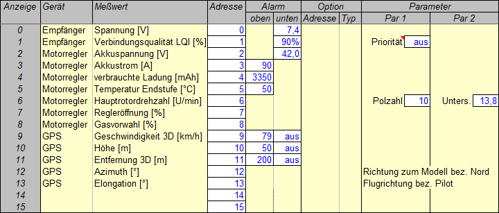
Das sind die neuen Einstellungen der Telemetriegeräte. Die vier Einträge für die beiden Spannungssensoren wurden entfernt und Azimuth und Elongation vom GPS wurden hinzugefügt.
Alarm ist jetzt eigentlich bedeutungslos da alle Alarme im neuen Sender eingerichtet sind. Sie sind aber auch in den Sensoren noch vorhanden, einfach weil sie dort nicht entfernt wurden.
Azimuth ist der wirklich interessante neue Wert. Im Fall eines Absturzes ist das die Richtung bezogen auf Nord, in der man das Modell suchen muß. Die Entfernung wird bisher schon angezeigt. Natürlich muß nach dem Absturz der Empfänger noch Telemetriewerte senden können, damit die Suche mit GPS funktioniert.
Beispiel
Das folgende Diagramm zeigt einen Auszug aus den Telemetriedaten eines Fluges, indem es die Werte von Empfängerspannung (blau) sowie von Spannung (grün), Strom (rot) und Entladung (rosa) der Antriebsakkus über der Flugdauer aufträgt. Es war ein normaler Flug mit lauter liegenden Achten, geflogen mit Reisegeschwindigkeit oder langsam und mit Schwebeflug dazwischen. Im Reiseflug war der Strom bemerkenswert gering und ebenfalls seine Schwankungen, deren Hoch- und Tiefpunkte Kurven und Geradeausflug entsprechen und bis auf 30 A gehen. Im Langsamflug und im Schweben ist der Strom wesentlich größer und die Schwankungen gehen bis auf ungefähr 40 A.

"Empfängerakkuspannung" (blau) ist eigentlich das, was der Empfänger über das Kabel für das Summensignal vom Kreiselsystem bekommt. Dorthin kommt es über einen MPX-Stecker und ein dickes Kabel von der Akkuweiche, an der zwei LiPo-Akkus 2s 2200 mAh 20C/40C mit XT60-Steckern hängen.
Der Sensor hat eine Auflösung von 0,1 V, deshalb ist die blaue Linie so gezackt. Vor und nach dem Flug ziehen die Elektronik (einschließlich Servos) und die Lichter nur einen geringen Ruhestrom. Während des Fluges ist die durchschnittliche Entladung immer noch recht gering, aber die Spannung schwankt um 0,3 V oder sogar 0,5 V. Offensichtlich lässt das Kreiselsystem die Servos schnell und hart arbeiten, um den von uns so geschätzten ruhigen und stabilen, aber auch agilen Flug zu bewirken. Interessanterweise bricht die Spannung weniger ein bei Langsamflug und Schweben (um 2:30 herum auf der Zeitachse). Da haben die Servos also weniger zu tun.
Die Empfängerakkus hatten an dem Tag bei 8,2 V begonnen und dies ist der zweite Flug, beginnend mit 7,9 V. Nach dem Flug ist die Ruhespannung fast 0,2 V geringer. Natürlich ist die Entladung nicht linear, sondern zuerst degressiv und dann progressiv. Der dritte Flug begann bei 7,8 V und endete bei 7,5 V Ruhespannung beziehungsweise 7,6 V Leerlaufspannung (3,8 V pro Zelle, Lagerspannung).
Die Spannung der Antriebsakkus misst der Regler an den dicken Kabeln, die von unten unter dem Boden des Helis kommen. Dort ist der Hauptschalter mit 5mm-Goldsteckern verbunden und die zwei LiPo-Akkus 6s 5000 mAh 40C/80C mit XT90-Steckern. Die grüne Linie zeigt einen typischen Entladungsverlauf über die gesamte Messdauer gesehen, aber es gibt viele mehr oder weniger tiefe Spannungseinbrüche, die genau den Stromspitzen (rot) entsprechen. Die Differenz der Leerlaufspannungen vor und nach dem Flug beträgt ungefähr 4,6 V. Das sind 0,38 V pro Zelle, also von 4,18 V Ladeschlußspannung auf 3,80 V Lagerspannung – Bingo!
Den Antriebsstrom (rot) zieht der Regler aus den Akkus. Die richtige Einstellung für langsamen Hochlauf habe ich nicht gefunden, deshalb drehe ich nun langsam am Senderknopf für die Rotordrehzahl. Es gibt Einbrüche und Überschießen, aber schließlich bleibt der Strom bei 16 A wenn die Drehzahl 1100 U/min erreicht. Start und Beschleunigen brauchen viel Strom, auch und besonders das Drehen auf der Stelle. Langsamflug und Schweben (um 2:30 herum auf der Zeitachse) sorgen für große Schwankungen. Reiseflug mit Kurven (3:00 bis 4:20) verursacht kleinen Strom und kleine Schwankungen (Stromspitzen in Kurven). Der Landeanflug (von 6:40 an) bringt große Stromspitzen mit sich, aber je näher am Boden desto kleiner wird der Strom. Nach dem Aufsetzen bleibt der Strom bei 11,5 A, weil die Blätter weniger angestellt sind als vor dem Start.
Die Entladung der Antriebsakkus (rosa) ist einfach der Strom über der Zeit aufsummiert, natürlich vom Regler. Die Linie beginnt langsam wie der Strom und stellt dann so etwas wie einen durchschnittlichen Strom dar, weil kurzwellige Schwankungen durch das Aufsummieren weggeglättet werden. Hoher Strom für eine halbe Minute (um 2:30 herum) macht die rosa Linie steiler, Reiseflug (3:00 bis 4:20) weniger steil. Alles in allem kommt die Linie dennoch einer geraden Diagonale gleich (außer am Anfang und Ende) und bietet sich damit zur Berechnung des durchschnittlichen Stromes an: 20,8 A in diesem Fall.
Regler
Die Bedienungsanleitung zum Regler YGE Opto 135 ist wohl nur für Eingeweihte verständlich. Aus ihr geht nicht hervor, wie ein langsamer Hochlauf für Helis eingestellt wird, und im Einstellprogramm gibt es zwar mehr Details, aber auch keine Erklärung. Immerhin habe ich es geschafft, den Governor-Store-Modus zu programmieren, und zwar indem ich überlegt habe, wie der Regler wohl arbeiten müsste. Falls jemand die gleichen Probleme hat wie ich, helfen vielleicht die beiden folgenden Diagramme.
Die hellgrüne Linie oben und die rote Linie unten zeigen wieder Akkuspannung und Strom während desselben Fluges wie im vorherigen Abschnitt. Dazwischen werden jetzt aber (dunkelrot) die Hauptrotordrehzahl sowie (grün) Gasvorwahl und (blau) Regleröffnung dargestellt. Die letzten beiden Begriffe werden durch das Diagramm erklärt.

Es zeigt nämlich, daß die Drehzahl (dunkelrot) nach dem Hochlauf sehr gut konstant gehalten wird. (Die Auflösung des Drehzahlwertes ist offenbar 10 U/min.) Genau so wird es durch die sogenannte Gasvorwahl (grün) vorgegeben. Diese stellt also eine Art Sollwert dar, hier 76% des maximal möglichen Wertes. Im Governor-Modus kann man diesen vielleicht als maximal mögliche Drehzahl interpretieren, allerdings nur "theoretisch" möglich mit der gleichen Akkuspannung wie beim "Einlernen" und ohne Last.
Die sogenannte Regleröffnung (blau) stellt dann den entsprechenden Istwert dar. Den kann man vereinfacht als Prozentsatz der maximal möglichen Spannung interpretieren. Die wird mit Entladung des Akkus geringer, also muß der Prozentsatz laufend erhöht werden. Die Linie ist recht gezackt, steigt aber tendenziell mit der Zeit (von links nach rechts) an. Dieser Verlauf ist genau spiegelbildlich zur oben liegenden (hellgrünen) Spannungslinie, denn um die Drehzahl konstant zu halten, muß der Regler umso mehr aufmachen, je weiter die Spannung absinkt.
Die Zacken in der unten liegenden (roten) Stromlinie (Doppelbedeutung des Wortes bewusst) entsprechen genau denen der Regleröffnung (blau), denn letztere ist nötig, um den Strom freizusetzen, der zum Einhalten der Drehzahl gebraucht wird, zum Beispiel wenn der Pitch erhöht wird. Entsprechend sieht man manchmal einen Einbruch (Zacken nach unten) der Drehzahl, bevor der Regler weiter öffnet und höherer Strom die Drehzahl wieder auf Sollwert bringt – manchmal so schnell, daß sie den Sollwert überschießt. Umgekehrt – plötzlich geringere Last durch weniger Pitch – gilt das Entsprechende.
Vermutlich sind Gasvorwahl und Regleröffnung gleich, wenn die Spannung gleich der beim "Einlernen" ist, gleiche Drehzahl vorausgesetzt. Das Einlernen bestand nur darin, einmal bis zu einer bestimmten Drehzahl hochzufahren, nachdem der Governor-Store-Modus eingestellt worden war. Nach Anleitung soll das bei einer Gasvorwahl von mehr als 70% erfolgen. Die ergab sich einfach bei 1100 U/min, wohl wegen der richtigen Auslegung von Motor und Getriebe. Diese Drehzahl kann man also als "Standard" (Begriff aus der YGE-Bedienungsanleitung, im Gegensatz zu Schweben und 3D) für diesen Heli ansehen, denn die dafür nötigen 76% Gasvorwahl liegen genau im empfohlenen Bereich von 70 bis 80%.

Zum Vergleich zeigt dieses Diagramm die Werte eines späteren Fluges mit der jetzt bevorzugten niedrigeren Drehzahl 1040 U/min. Die wird mit 72% Gasvorwahl erreicht, also immer noch im "Standard"-Bereich, und das Flugverhalten fühlt sich auch noch wie "Standard" an. Für niedrige Drehzahlen (für das Schweben) wird in der YGE-Bedienungsanleitung der Bereich 60 bis 70% empfohlen. Das könnte man mit diesem Heli durchaus noch ausprobieren, denn bisher fühlt er sich im Flug noch lange nicht "weich" an. Jedenfalls ist dieser Heli auf der sicheren Seite, denn Gasvorwahl und Regleröffnung dürfen nicht zu klein sein.
Für schwere Scale-Helis wird deshalb eine möglichst große Regleröffnung (ja, nicht Gasvorwahl) empfohlen, um höhere Wärmeverluste zu vermeiden. Das kann hier kein Problem sein, denn die Temperatur des Reglers ging bei diesem Flug nicht über 33°C, beim vorherigen nicht über 36°C. Natürlich könnte man eine schwere Last unter diesen Heli hängen, aber dann würde man auch mit relativ hoher Drehzahl fliegen, also hoher Gasvorwahl und damit auch Regleröffnung. Die Drehzahl könnte deutlich über 1100 U/min liegen, bei 1200 U/min oder sogar mehr, denn der Antrieb hat die dafür nötige Leistungsreserve (siehe nächstes Kapitel).
Sobald all das ausprobiert ist, sind die Telemetriewerte von Gasvorwahl und Regleröffnung eigentlich nicht mehr nötig. Dennoch werde ich sie nicht "abschalten", denn sie werden aufgezeichnet und im Fall eines technischen Problems am Antrieb des Helis oder eines Unfalls könnten gerade diese aufgezeichneten Daten wichtig oder zumindest nützlich sein.
Die "Regleröffnung" spielt auch im nächsten Kapitel (über den Antrieb) eine Rolle. Dort heißt der Wert "Leistungsgrad" als der Prozentsatz der vollen Antriebsspannung, der den für eine bestimmte Drehzahl nötigen Strom zur Folge hat. Während hier die volle Spannung laufend absinkt, wird dort von vorneherein konstant die Nenn-Zellenspannung von LiPo (3,70 V) vorausgesetzt – ein so niedriger Wert, daß er hier nicht erreicht wird (nur 3,80 V). Deshalb ist die "Regleröffnung" hier geringer als der "Leistungsgrad" dort, steigt aber laufend an.
Antrieb
Um die Leistung des Modells im Flugsimulator REFLEX XTR² richtig abzubilden, mussten die Antriebskennwerte ermittelt werden. "Antrieb" meint den Elektromotor, Haupt- und Heckrotorgetriebe und -wellen sowie beide Rotorköpfe. Manche Kennwerte waren vom jeweiligen Hersteller angegeben, andere mussten gemessen werden und der Rest wurde berechnet. Nachdem der Hubschrauber zum ersten mal geflogen war, gab es im Fluge aufgezeichnete Telemetriedaten. Damit konnten realistische betriebliche Werte berechnet werden. Die Rechentabellen gibt es zum Herunterladen.
Als Akkuspannung wird in den folgenden Abschnitten die Nenn-Zellenspannung von LiPo (3,70 V) vorausgesetzt, multipliziert mit der Zellenzahl (12). Um die Akkus zu schonen, soll nur bis auf 3,75 V pro Zelle entladen werden, ausgehend von 4,20 V oder weniger. Praktisch ist die Spannung also immer (bis zu 13,5%) höher, als hier "theoretisch" angenommen.
Kennwerte
Der Motorhersteller hatte 450 U/min/V als spezifische Drehzahl (kv) und 32 mΩ als Innenwiderstand (Impedanz, Ri) angegeben. Der dritte Kennwert, der zum Berechnen der Motorleistung nötig ist, der Leerlaufstrom (I0), musste gemessen werden. Zu diesem Zweck wurde der Motor einfach an der Werkbank befestigt und mit dem vorgesehenen Regler (Governor) sowie einem 10s LiPo-Akku auf Drehzahl gebracht. Die Telemetrie des Reglers lieferte die Werte von Drehzahl und Strom. I0 war dann 2,3 A bei 15800 U/min (gleichbedeutend mit 1143 U/min Hauptrotordrehzahl).
Entsprechend wurde der Strom gemessen, nachdem die Mechanik fertig montiert war (siehe oben, wo auch die Untersetzungsverhältnisse genannt sind). Der Regler (Governor) wurde auf 1100 U/min Hauptrotordrehzahl eingestellt und nach einem kurzen Einlaufen des ganzen Antriebs wurden jetzt 3,3 A Leerlaufstrom (ohne Rotorblätter) gemessen. Das "Getriebe" von Haupt- und Heckrotor verursachte also zusätzlich 1,0 A Stromaufnahme. Eine einfache Rechnung ergab 94,5% "Getriebe"-Wirkungsgrad (der, als Prozentsatz der Momenten-Übertragung, per Definition alle zusätzlichen Reibungsverluste unter Last einschließt).
Diese Kennwerte, die angegebenen Getriebeuntersetzungen und die gemessenen Längen und Breiten der Rotorblätter genügen, um den Antrieb im Flugsimulator abzubilden. Die angegebenen Werte (außer die Getriebeuntersetzungen) habe ich nicht einmal überprüft, weil das schwierig gewesen wäre und weil die Berechnungen ohnehin vereinfacht sind.
Maximalwerte
Im Simulator wird die Kennlinie der mechanischen Motorleistung angenähert und dafür muß die maximale mechanische Leistung angegeben werden sowie die Drehzahl, bei der sie erreicht wird. Um diese zu ermitteln genügen die Antriebskennwerte. Allerdings muß der Widerstand von Akkus, Regler und Leitungen (mit Steckern) geschätzt werden. Entsprechend der Anzeige des Ladegerätes wurden 30 mΩ pro Akku eingesetzt sowie 20 mΩ für den Regler samt Leitungen und Steckern angenommen.
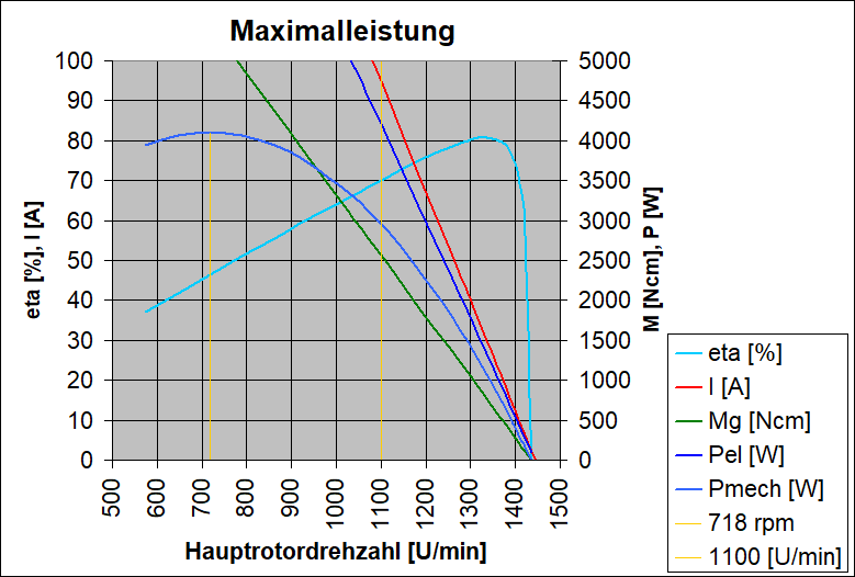
Rechnerisch ergibt sich dann die maximale mechanische Leistung (nur Motor, ohne Getriebe) zu 4349 W bei 9932 U/min (entsprechend einer Hauptrotordrehzahl von nur 718 U/min). Diese beiden Werte werden nur für den Simulator gebraucht. (Das Diagramm zeigt Werte für Motor und Getriebe gemeinsam.)
Praktisch kann der Motor diese Leistung nicht abgeben, weil der Strom viel zu hoch wäre. Selbst bei der vorgesehenen Rotordrehzahl von 1100 U/min wäre der Strom mit 95 A noch zu hoch. Wenn der Regler bei konstant 1100 U/min nur kurzzeitig "Vollgas" geben würde, wäre das aber unschädlich für den Motor (für den Regler ohnehin). Im Durchschnitt ist der Strom nicht einmal ein Viertel so hoch.
Deshalb ist es auch kein Problem, daß hier zu niedrige ("konservative") Werte errechnet werden, weil nur die Nenn-Zellenspannung von LiPo (3,70 V) vorausgesetzt wird und keine praktische Betriebsspannung (zwischen 3,75 V und 4,20 V). Praktisch wären die Werte also bis zu 13,5% (4,20 V) höher, die meiste Zeit während des Fluges zwischen 8% (4,00 V) und 3% (3,80 V).
Rundflug
Im Flug arbeitet der Antrieb mit Teillast, die aber von der Drehzahlregelung für den Hauptrotor ständig verändert wird, um die empfohlenen und gewünschten 1100 U/min einzuhalten. Hier wird einfach der durchschnittliche Strom eines typischen Übungsfluges angenommen: 21,6 A. Der "Leistungsgrad" ist dann der Prozentsatz der vollen Antriebsspannung, der diesen Strom bei dieser Drehzahl zur Folge hat. Ermittelt wird er durch einfaches Ausprobieren: 82% für 21,6 A und 1100 U/min.
Der "Leistungsgrad" entspricht der oben beschriebenen "Regleröffnung". Ersterer bezieht sich aber auf die angenommene Akku-Nennspannung (3,70 V pro Zelle), letztere auf die wirkliche, (von 4,20 V auf 3,75 V pro Zelle) ständig abnehmende Akkuspannung. Diese ist immer höher als die Nennspannung, weshalb die Regleröffnung immer kleiner ist als der Leistungsgrad und ständig erhöht wird. Gerade durch das ständige Nachregeln werden aber die Drehzahl und die anderen Werte – zumindest im Mittel – konstant gehalten. Deshalb können wir den konstanten Leistungsgrad als praktischen Ersatz für die veränderliche Regleröffnung verwenden. Beide sind gleichwertige Leistungseinstellungen, wobei ersterer eine Art Nennwert ist (nicht zu verwechseln mit der oben beschriebenen Gasvorwahl).
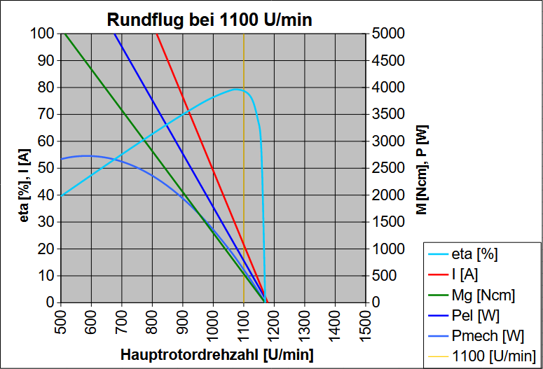
Das ist also das Diagramm für 82% Nenn-Leistungseinstellung (bei 3,70 V Akkuzellenspannung) und 21,6 A Strom, nötig für Rundflug mit 1100 U/min und während des Fluges vom Regler automatisch eingestellt.
"Vollgas geben" (100%) bei konstant 1100 U/min, um mit maximalem Blattanstellwinkel stark zu steigen, könnte bei 3,70 V Akkuzellenspannung bis zu 95 A ziehen. Diese große (und praktisch noch größere) Leistungsreserve (4,4-facher Strom, 4,8-fache mechanische Leistung) ist im vorherigen Diagramm gezeigt.
Das Diagramm zeigt, daß der Antrieb mit relativ kleiner Leistung und deshalb relativ hoher Motordrehzahl arbeitet – im Verhältnis zur Höchstdrehzahl, die von der jeweils nötigen Spannung abhängt. Das ist der Bereich, wo die Wirkungsgradkurve eta (hellblau) ihr Maximum hat, und das sind 79% gesamt, also alle elektrischen Widerstände und alle mechanische Reibung berücksichtigt. Somit ist der Motor eine ausgezeichnete Wahl für diesen Hubschrauber, sowohl wegen seiner passenden spezifischen Drehzahl kv als auch wegen seines hohen Wirkungsgrades. Das ergibt minimalen Strom und maximale Flugdauer für jede praktikable Rotordrehzahl. Für noch längere Flugdauer könnten noch kleinere Rotordrehzahlen gewählt werden, die noch geringeren Strom erfordern (siehe unten).
Mit dem "Leistungsgrad" werden alle Kurven im Diagramm in waagerechter Richtung "geschrumpft". Die maximale Drehzahl ist also hier 82% von der im "Vollgas"-Diagramm oben. Bei nach wie vor 1100 U/min arbeitet der Antrieb jetzt ein klein wenig über der Drehzahl des höchsten Wirkungsgrads, aber der Wirkungsgrad ist nicht merklich geringer als der Maximalwert: immer noch 79%.
Schweben
Im Schwebeflug ohne Bodeneffekt ist der durchschnittliche Strom merklich (4,9 A) höher als im Rundflug: 26,5 A. Dennoch ist der durch einfaches Ausprobieren ermittelte "Leistungsgrad" nur geringfügig (1%) höher: 83% für 26,5 A und 1100 U/min.
Wie gut der "Leistungsgrad" der "Regleröffnung" entspricht, wurde mit den aufgezeichneten Telemetriedaten im Diagramm oben überprüft. Dort gibt es (um 6:50) eine kurze Zeit des Schwebens ohne Bodeneffekt mit dem hier angenommenen Strom von 26,5 A. Die Akkuspannung ist derweil 44,5 V, steigt aber im Leerlauf nach dem Flug auf 45,5 V. Hier wird eine Spannung von 44,4 V angenommen; geteilt durch 45,5 V dort macht 0,976. 81,4% Regleröffnung dort geteilt durch 82.8% Leistungsgrad hier macht 0,983. Das ist eine recht gute (0,7%) Übereinstimmung, wenn man berücksichtigt, daß hier 60 mΩ Akku-Innenwiderstand angenommen wurde, er dort aber nur 38 mΩ zu sein scheint (1,0 V Spannungsabfall geteilt durch 26,5 A).
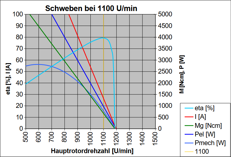
Dies ist das Diagramm für 83% Leistungseinstellung und 26,5 A Strom, nötig für Schwebeflug mit 1100 U/min und vom Regler automatisch eingestellt.
Die Leistungsreserve ist immer noch groß (3,6-facher Strom, 3,8-fache mechanische Leistung) und möglicherweise nützlich, um einem Wirbelringzustand zu entkommen.
Hier sind die Kurven auf 83% in waagerechter Richtung "geschrumpft", also liegen sie 1% weiter rechts als die im vorherigen Fall des Rundflugs. Nur 1% mehr Spannung ist nötig, um den Strom um 4,9 A zu erhöhen, weil die Drehzahl nicht erhöht wird. Bei nach wie vor 1100 U/min arbeitet der Antrieb jetzt ziemlich genau mit der Drehzahl des höchsten Wirkungsgrads: der ist 79%.
Rundflug 2
Auch hier wird einfach der durchschnittliche Strom eines typischen Übungsfluges angenommen, nun aber bei 1040 U/min (9% weniger) am Hauptrotor. Der Strom ist merklich (2,0 A – 9%) geringer als bei 1100 U/min: 19,6 A. Auch der "Leistungsgrad" ist jetzt merklich (5%) geringer: 77% für 19,6 A und 1040 U/min.
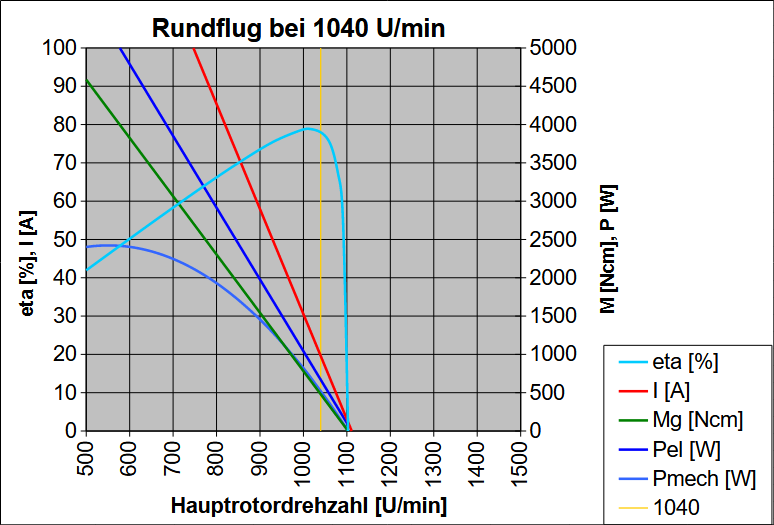
Dies ist das Diagramm für 77% Leistungseinstellung und 19,6 A Strom, nötig für Rundflug mit 1040 U/min und vom Regler automatisch eingestellt.
"Vollgas geben" (100%) bei konstant 1040 U/min könnte bis zu 111 A ziehen. Diese riesige Leistungsreserve (5,7-facher Strom, 6,3-fache mechanische Leistung) ist wohl praktisch nicht nutzbar, denn ein Überziehen (overpitching) könnte bei diesem Strom vorkommen, sollte aber durch Begrenzen des Blattanstellwinkels verhindert werden. Der Strom ist nicht zu hoch für den Regler und sogar der Motor könnte kurze Stromstöße dieser Höhe vertragen.
Hier sind die Kurven auf nur noch 77% in waagerechter Richtung "geschrumpft", weil die Rotordrehzahl nur noch 1040 U/min beträgt und weil dafür 2,0 A weniger Strom nötig sind. Die Drehzahl 1040 U/min liegt jetzt sogar ein klein wenig weiter über der Drehzahl des höchsten Wirkungsgrads als 1100 U/min, aber der Wirkungsgrad ist kaum (1%) geringer: 78%.
Rundflug 3
Auch hier wird einfach der durchschnittliche Strom eines typischen Übungsfluges angenommen, nun aber bei 1160 U/min (5,5% mehr) am Hauptrotor. Der Strom ist etwas (0,9 A – 4%) größer als bei 1100 U/min: 22,5 A. Der "Leistungsgrad" ist etwas (5%) größer: 86% für 22,5 A und 1160 U/min.
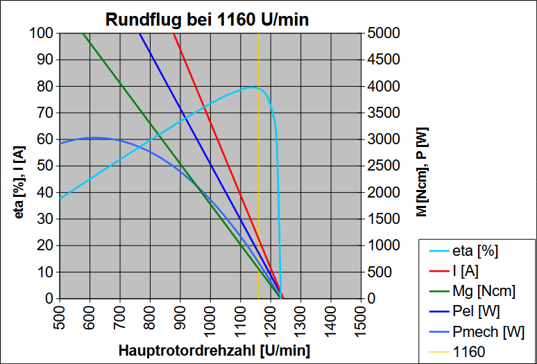
Dies ist das Diagramm für 86% Leistungseinstellung und 22,5 A Strom, nötig für Rundflug mit 1160 U/min und vom Regler automatisch eingestellt.
"Vollgas geben" (100%) bei konstant 1160 U/min könnte bis zu 78 A ziehen. Diese Leistungsreserve (3,5-facher Strom, 3,8-fache mechanische Leistung) ist praktisch nutzbar, denn ein Überziehen (overpitching) wird bei diesem Strom nicht vorkommen. Der Strom ist nicht zu hoch für den Regler und sogar der Motor könnte ihn vertragen.
Hier sind die Kurven auf 86% in waagerechter Richtung "geschrumpft", weil die Rotordrehzahl nun 1160 U/min beträgt und weil dafür 0,9 A mehr Strom nötig sind. Die Drehzahl 1160 U/min liegt genauso weit über der Drehzahl des höchsten Wirkungsgrads wie bei 1100 U/min und der Wirkungsgrad ist gleich: 79%.
Rundflug 4
Auch hier wird einfach der durchschnittliche Strom eines typischen Übungsfluges angenommen, wieder bei 1100 U/min am Hauptrotor, aber jetzt mit einem 700-52 kv 520 Motor (15,5% mehr). Der Strom ist merklich (3,4 A – 15,7%) höher als mit kv 450: 25.0 A. Aber der "Leistungsgrad" ist jetzt merklich (10%) geringer: 72% für 25.0 A und 1100 U/min.
Hier wird der KONTRONIK Pyro 700-52 (kv 520) vorausgesetzt. Er hat dieselben Abmessungen wie der Pyro 700-45 (kv 450), aber weniger Windungen in der Statorwicklung und aus dickerem Draht. Da der Hersteller nur noch kv angibt, wurde für den -52 der Innenwiderstand von der alten Webseite im Web Archive genommen und der Leerlaufstrom einfach 15% größer als beim -45 geschätzt.
In der Rechentabelle wurden dann Leistungsgrad und Strom durch Probieren so eingestellt, daß sich bei 1100 U/min Rotordrehzahl die gleiche mechanische Leistung ergibt wie im Fall des -45. Das ist schließlich das, was der Heli zum Rundflug braucht. Die dafür nötige elektrische Leistung ist hier geringfügig (1,7%) höher, weil die Widerstandsverluste mit dem Quadrat des Stromes steigen. Der Wirkungsgrad ist folglich um 1,6% schlechter. So genau ist die Rechnung aber nicht, weil der Leerlaufstrom grob geschätzt ist.
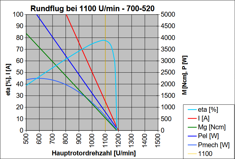
Dies ist das Diagramm für 72% Leistungseinstellung und 25,0 A Strom, nötig für Rundflug bei 1100 U/min mit einem kv 520 Motor und vom Regler automatisch eingestellt.
"Vollgas geben" (100%) bei konstant 1100 U/min könnte bis zu 145 A ziehen. Diese Leistungsreserve (5,8-facher Strom, 6,4-fache mechanische Leistung) ist dem vorherigen Fall mit 1040 U/min Rotordrehzahl und dem kv 450 Motor recht ähnlich.
In beiden Fällen erfordert die relativ geringe Drehzahl ein stärkeres Abregeln der Spannung. Die volle Spannung ergibt dann eben eine größere Steigerung von Strom und Leistung.
Hier sind die Kurven auf nur noch 72% (statt 82%) in waagerechter Richtung "geschrumpft", weil die kv jetzt 520 (statt 450) ist. Das heißt aus derselben Spannung würde jetzt eine (um 15,5%) höhere Rotordrehzahl folgen, deshalb ist für dieselbe Rotordrehzahl (1100 U/min) ein kleinerer Leistungsgrad nötig. Umgekehrt ist 3,4 A (15,7%) mehr Strom nötig. Die Drehzahl 1100 U/min liegt wieder etwas über der Drehzahl des höchsten Wirkungsgrads und ist etwas kleiner: 78% (statt 79%).
Der höhere Strom ist weder für den Motor noch für den Regler ein Problem. Letzterer könnte aber ein Problem mit dem Leistungsgrad haben. Der liegt zwar noch über 70%, wegen der höheren Akkuspannung im Betrieb liegen aber Regleröffnung und Gasvorwahl im Rundflug ("Standard" für den Regler) bereits unter 70%. Das kann laut YGE zu starker Erwärmung (des Reglers und vielleicht auch des Motors) führen, gegen die eine größere Getriebeuntersetzung ("abritzeln") empfohlen wird – oder weniger kv. (Beides ist gleichwertig, wie auch kleinere Akkuspannung.) Also haben wir hier schon zu viel kv – für den Regler, der die Spannung weiter abregeln und höheren Strom vertragen muß.
Nachprüfung
Alle Telemetrie-Messwerte und die darauf basierenden Berechnungen legen nahe, daß ein Motor der Größe 700 mit 450 kv für diesen Hubschrauber gerade richtig ist. Ein größerer Motor oder einer mit höherem kv scheint eher nutzlos, wenn nicht sogar schädlich. Um das zu überprüfen, habe ich schließlich noch das auf der Website des Motorherstellers (Kontronik) kostenlos angebotene Programm heliCalc hergenommen. Es ist allein schon deshalb gut, weil es von den Motoren den Innenwiderstand und den Leerlaufstrom enthält, die sonst nicht mehr auf der Website angegeben sind, sowie den Innenwiderstand von Reglern und Akkus. Vor allem aber soll es eine Hilfe bei der Motorauswahl sein, weil man verschiedene Motoren probieren und die errechneten Kennwerte vergleichen kann. Also habe ich die Daten des hier verwendeten Antriebs eingegeben.
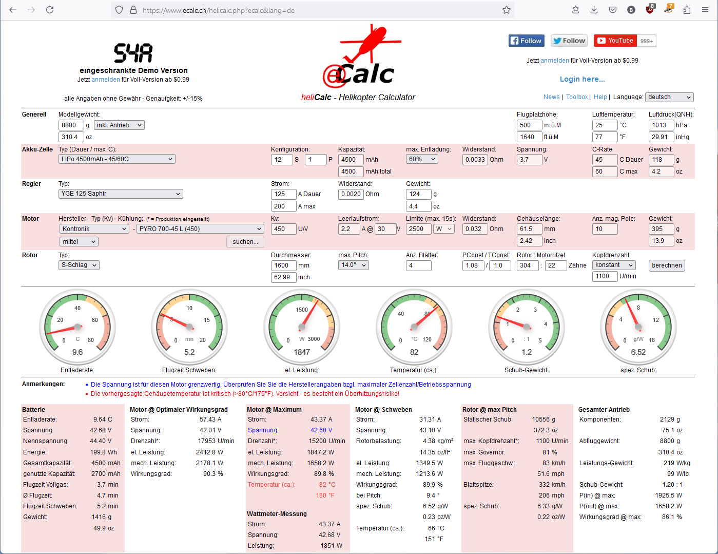
Es wurde dann aber die allgemeine freie Version von heliCalc verwendet (statt der Kontronik-Version, welche auch frei ist), denn sie kennt außer dem Motor auch meinen YGE-Regler und einen ganz gut passenden 4500 mAh LiPo-Akku. Beide Versionen sind eingeschränkt insofern als der Anpassungsfaktor für den Rotor (PConst/TConst) nicht veränderbar ist. Man kann auch keine Blatt-Tiefe angeben.
Etwas anders als in meinen eigenen Berechnungen sind der Leerlaufstrom des Motors (2,2 A statt 2,3 A) und der Innenwiderstand des Akkus (33 mΩ statt meiner zunächst zu hohen 60 mΩ, aber dann 38 mΩ nach den Telemetriedaten und dem Ladegerät).
Mir fiel es leicht, im Nachhinein die Antriebsparameter so zu berechnen, daß sie der Rotordrehzahl und dem gemessenen Strom entsprechen. Diese Berechnungen erwiesen sich als richtig (siehe oben). Hingegen versucht heliCalc, den Strom und die weiteren Parameter vorherzusagen, indem es den Leistungsbedarf des Rotors schätzt. Das scheint aber schwieriger zu sein als gedacht.
Jedenfalls errechnet das Programm höheren Strom als gemessen (31,3 A statt 26,5 A) und entsprechend zu viel mechanische Leistung (1214 W statt 818 W) in der Spalte Schweben. Die Werte in den anderen Spalten stimmen auch nicht. Vier der sechs Anzeigen sind im gelben Bereich (Warnung). Und das Programm warnt vor zu hoher Spannung (obwohl der Motorhersteller 12s LiPo angibt) und zu hoher Motortemperatur (in der Spalte Maximum). Oben auf der Webseite steht 15% Genauigkeit, aber diese Ergebnisse liegen weit außerhalb und sind einfach nicht realistisch.
Vielleicht arbeitet die Rechnung für konstante Drehzahl nicht richtig, aber das ist nur geraten und ich könnte genauso gut das Programm nicht verstanden haben. In jedem Fall scheint es einen größeren, stärkeren Motor für nötig zu halten. Im Text wird gewarnt, daß der errechnete Strom zu klein sein kann und man deshalb vor dem Erstflug den wirklichen Strom messen soll. Hier scheint es, als ob auch vor zu großem errechneten Strom gewarnt werden sollte. Nur gut daß ich nicht von vorneherein auf die Website von Kontronik gegangen bin, sondern Herrn Illig von Scaleflying.de nach einem passenden Motor gefragt und den dann gleich gekauft habe.
Schätzung
Immer noch auf der Suche nach einem formalen Weg, einen passenden Motor zu finden, kam ich auf einfache Berechnungen zurück. Zumindest der erste Schritt – Bestimmen von kV – scheint verlässlich, weil dieser Parameter auf bekannten (gegebenen) Werten beruht. Zudem ist kV sehr bestimmend für einen Motor, weil dieser Kennwert ausdrückt, wie schnell der Motor dreht, proportional zur Spannung. Und als Kehrwert drückt er aus, wie viel Drehmoment der Motor erzeugt, proportional zum Strom. (Deshalb zieht ein Motor mit höherem kV mehr Strom, um das gleiche Drehmoment bei der gleichen Drehzahl zu erzeugen.) Ist kV einmal festgelegt, wird im nächsten Schritt eine Obergrenze für den Innenwiderstand R geschätzt. Der bestimmt, wie viel Strom fließt, proportional zur Spannung. Beide Kennwerte zusammen drücken Größe und Leistung eines Motors aus. (Die folgenden Gleichungen werden abgeleitet in meiner Ausarbeitung ElectricDrive.pdf, Kapitel "Motor/Gear Illustration", Abschnitt "Motor Selection".)
Die erste hier verwendete Gleichung ist ein einfacher Quotient. Sein Zähler ist die Drehzahl des Motors, das Produkt von Soll-Rotordrehzahl nsoll und Getriebeuntersetzung ig. Der Nenner ist praktisch die Motorspannung. Die Akkuspannung Ua wird durch den oben definierten Leistungsgrad LG verringert. Hier ist 0.8 (80%) erforderlich, weil wir 44,4 V Nennspannung für den 12s LiPo-Akku ansetzen. Im Betrieb ist die Spannung stets höher, aber dann bleibt der LG im für den Regler gewünschten Bereich zwischen 70% und 80%.
Die Wurzel aus dem maximalen Motorwirkungsgrad ηm max ist das Verhältnis, das angibt, wie weit die Drehzahl des maximalen Wirkungsgrads unter der Maximaldrehzahl liegt. Das heißt, wir wollen, daß der Motor bei der erforderlichen Drehzahl seinen maximalen Wirkungsgrad hat! Das ist die richtige (nicht vereinfachte) Formel, aber der Wert des Wirkungsgrades muß geschätzt werden. Der maximale Wirkungsgrad des Motors allein wird auf 92% geschätzt, aber 5% werden abgezogen für den Widerstand von Akku, Regler und Kabeln mit Steckern. Weitere 2% werden abgezogen, weil die Motorspannung durch den LG reduziert ist.
Demnach sind 464 erforderlich, das ist viel näher an 450 als an den nächsthöheren Werten von kV (500 oder 520) in der Kontronik Pyro Baureihe von Hubschraubermotoren. Und es ist besser, ein etwas kleineres kV zu wählen, weil dann der Leistungsgrad LG im gewünschten Bereich bleibt. Ein größeres kV hätte zur Folge, daß der Regler auch unter 70% LG arbeiten muß und dann womöglich viel Wärme erzeugt. Der Leistungsgrad LG wird ganz einfach mit dem gewählten Ist-kV korrigiert:
Obwohl der Leistungsgrad (82,6%) jetzt schon relativ nahe an "Vollgas" (100%) liegt, ist noch eine gewisse Leistungsreserve vorhanden, denn die Leistung steigt (bei konstanter Drehzahl) mit dem Quadrat der Spannung, also des Leistungsgrads. Selbst in diesem schlechtesten Fall (82,6% LG bei 3,7 V Zellenspannung) lässt sich die Motorspannung immer noch um 21% (auf 100% LG) steigern und die Leistung steigt dann noch um 46%. Und die Motorgröße wird nicht nur eben so ausreichen, weil die nächst größere aus der Baureihe gewählt werden muß, also wird die Leistungsreserve noch größer sein.
Der Hersteller des Hubschraubers empfiehlt in der Anleitung einen Motor mit kV 450 und der Größe 750. Den ersten Teil haben wir jetzt nachvollzogen, allerdings nur aufgrund der vorgegebenen Empfehlung für 1100 U/min Hauptrotordrehzahl. Wären wir von 1200 U/min ausgegangen, dann wäre statt 464 als erforderliches kV 507 herausgekommen. Wir legen uns aber auf kV 450 fest und haben aus der Kontronik Pyro Baureihe vier Größen zur Auswahl (700, 750, 850, 900) oder sogar fünf, wenn wir auch kV 480 (800) akzeptieren, was genauso nahe an 464 ist wie 450.
Auch der nächste Schritt beruht auf einem gegebenen Wert, dem erforderlichen (mittleren) Drehmoment Mg erf (g für Getriebewelle) im Schwebeflug. Es wurde oben aus aufgezeichneten Telemetriedaten berechnet, die bei 1100 U/min Hauptrotordrehzahl gemessen wurden. In der Gleichung für das Drehmoment konnte dieses einfach gegen den Widerstand ausgetauscht werden. Das gewählte kV und der entsprechend korrigierte Leistungsgrad LG müssen im folgenden verwendet werden. Der geschätzte maximale Motorwirkungsgrad ηm max und seine Wurzel ersetzen nun das Produkt von Widerstand und Leerlaufstrom, das noch nicht bekannt ist, solange kein Motor gewählt wurde.
Per Definitionem schließt der Widerstand R die Widerstände von Akku, Regler, Kabeln und Steckern ein. Sie müssen von den errechneten 105 mΩ abgezogen werden. Ich hatte 20 mΩ für den Regler angenommen, heliCalc auch. 38 mΩ für die Akkus wurden angesetzt, nachdem die Anzeige des Ladegerätes wiederholt während des Ladevorgangs beobachtet wurde.
47 mΩ ist eine Obergrenze für den Innenwiderstand des Motors. Der Wert lässt gerade genug Strom zu, um das erforderliche Drehmoment mit dem vorgesehenen Leistungsgrad LG zu erzielen, und bietet immer noch eine gewisse Leistungsreserve. In der Kontronik Pyro Baureihe hat schon der kleinste Motor mit kV 450 – Größe 700 – einen kleineren Innenwiderstand (32 mΩ), also ist die Größe 750 nicht nötig und die Leistungsreserve ist größer. Deshalb muß der Leistungsgrad erneut angepaßt werden, jetzt an den kleineren Widerstand R, der den erforderlichen Strom (der wiederum in Drehmoment umgewandelt wird) bei etwas kleinerer Spannung zulässt. Die Werte für Rm und I0 stammen von heliCalc:
Diese Gleichung für den Leistungsgrad LG ist ein Verhältnis von Spannungen. Der Nenner ist einfach die Akkuspannung, der Zähler (in Klammern) ist die Spannung, die für das erforderliche Drehmoment nötig ist. Der erste Term in Klammern ist die im Motor wirksame Spannung, das heißt sie bewirkt Drehmoment, indem sie den entsprechenden Strom zulässt. Der zweite Term ist der durch Innenwiderstand und Reibung verursachte "Spannungsabfall" und der dritte Term ist die bei Solldrehzahl durch Gegeninduktion generierte Spannung.
Die wirkliche Leistungsreserve kann jetzt direkt berechnet werden, nicht mehr in Analogie zum Leistungsgrad. Eine Hälfte der Gleichung für das Drehmoment Mg wird aus diesem Verhältnis herausgekürzt – Zähler und Nenner unterscheiden sich nur noch durch den Leistungsgrad LG. Wieder erkennen wir die Akkuspannung (unverändert sowie um den LG verkleinert), den "Spannungsabfall" und die Gegeninduktionsspannung. Die beiden letzteren Terme werden abgezogen und die wirksame Spannung, die Drehmoment erzeugt, bleibt übrig. Dieser wirksame "Rest" ist überraschend klein, besonders die durch den Leistungsgrad verkleinerte Spannung, die immerhin für Schwebeflug ausreicht. Entsprechend ist die Leistungsreserve erstaunlich groß:
Sie ist sogar größer als oben errechnet. Dort hatte ich den selbst gemessenen Leerlaufstrom I0 (2,3 A statt 2.2 A wie in heliCalc angegeben) und einen höheren Innenwiderstand des Akkus Ra (60 mΩ statt 38 mΩ laut Ladegerät) angenommen, wie für einen schlechteren Akku mit kleinerer C-Rate. Das Produkt beider Werte R⋅I0 ist merklich erhöht (von 0,198 V auf 0,258 V) aber absolut gesehen klein, so daß der große Unterschied zwischen den Werten der Leistungsreserve damit nicht erklärt werden kann. Der absolut kleine Anstieg des "Spannungsabfalls" erfordert aber eine entsprechend kleine Erhöhung des Leistungsgrades LG (von 0,815 auf 0,828), die eine relativ große Erhöhung der wirksamen Spannung darstellt – nötig um das Drehmoment für Schwebeflug zu erzeugen. Jetzt werden dieser Leistungsgrad sowie die daraus folgende Leistungsreserve genau so wie oben errechnet:
Das beweist nicht, daß diese Berechnung richtig ist, denn ich habe nur die Berechnung oben "umgekehrt". Aber es zeigt, wie empfindlich die Rechnung – und der Antrieb – auf Änderungen an den vorgegebenen Konstanten reagieren. Es ist gut möglich, daß ein weniger hochwertiger Motor, Regler und Akku (jeweils mit höherem Innenwiderstand und der Motor mit höherem Leerlaufstrom als hier) einen 750er Motor erforderlich machen würden, damit genug Leistungsreserve bleibt. (Als ich einmal in Panik voll Pitch gegeben habe, beanspruchte das eine Leistungsreserve von 3,5.) Höheres kV würde nur für höhere Rotordrehzahl gebraucht.
Überhaupt glaube ich, daß eine Berechnung, die auf angegebenen und angenommenen Werten beruht, nicht ganz richtig sein kann. Zumindest passe ich die Berechnung immer an, kalibriere sie mit gemessenen Daten, wie oben gezeigt. Trotzdem kann sie danebenliegen, zum Beispiel wenn es kalt ist und der Akku höheren Innenwiderstand als gewöhnlich hat.
Noch schwieriger zu rechnen als der Antrieb ist der Rotor, das heißt das erforderliche Drehmoment abgeleitet von angemessener Drehzahl und Blattwinkel sowie die erforderliche Leistungsreserve. Es war mir zu viel Arbeit, dafür Formeln zu entwickeln. Statt dessen wurde der Simulator eingesetzt, der alle Einflüsse weit genauer und umfangreicher berücksichtigt, als ich es je tun würde. Intern hat er also alle nötigen Daten, aber er zeigt nur wenige davon an. Nützlich sind sie dennoch und man hat gleich einen Eindruck von den zu erwartenden Flugleistungen und -eigenschaften.
Simulation
Das Modell wurde im Flugsimulator REFLEX XTR² abgebildet, um dort seine Flugleistungen zu untersuchen. Dazu gehörte, verschiedene Rotordrehzahlen auszuprobieren und zu sehen, welche Blattwinkel jeweils an Haupt- und Heckrotor nötig sind. Aber auch jedem anderen ist es sehr gut möglich, ebenfalls den Simulator benutzen, einfach um sich mit den Flugeigenschaften des Modells vertraut zu machen, um Autorotationslandungen zu üben oder sogar um verschiedene Rotordrehzahlen, Gewichte und Motoren auszuprobieren. Hier ist alles, was man dazu wissen muß, falls man es nicht schon weiß:
Simulator
REFLEX XTR² kann man einfach herunterladen. Mit der Installation auf dem Computer beginnt eine 14 Tage dauernde kostenlose Probezeit. Danach müsste man im Webshop eine Lizenz kaufen.
Die Installation auf einem aktuellen Windows-Computer ist einfach (aber Apple und Linux gehen nicht). Der Simulator braucht auch keine besonders leistungsfähige Grafikkarte. Vielmehr passt er sich der vorhandenen Grafikkarte an und läuft einfach – je besser die Grafikkarte desto besser die Grafik.
Einige moderne Sender haben einen Simulations- oder Game-Controller-Modus, in dem sie sich über ein einfaches USB-Kabel ohne Adapter mit einem Computer verbinden können. Um einen solchen Sender drahtlos zu verbinden oder um alle anderen Sender anzuschließen, braucht man einen Game-Controller-kompatiblen USB-Adapter. Es gibt solche mit Kabel, aber auch bequeme drahtlose (praktisch ein 2,4GHz-Empfänger in oder an einem USB-Stick). Dazu wissen die REFLEX FAQ mehr.
Im Sender (möglichst 8 Kanäle) muß man nur einen Modellspeicherplatz anlegen – für alle Simulatormodelle in REFLEX XTR². Er sollte vom Typ Flugzeug sein, nicht Hubschrauber! Und es soll eine einfache Konfiguration sein, ohne Mischer, auch ohne Expo. Es soll nur einen Querruderkanal geben, aber auch einen Landeklappenkanal (an einem Schieber oder Drehknopf) und einen Fahrwerkskanal (an einem Schalter). Bei Hubschraubern werden sie in anderer Rolle (Kreiselempfindlichkeit statt Landeklappen) oder derselben Rolle (Fahrwerk) benutzt und man sollte noch einen weiteren Kanal (an einem Schalter) für Autorotation haben.
Nachdem der Sender mit dem Computer verbunden ist (einschließlich Binden bei einem drahtlosen Adapter), wird der Simulator eine allgemeine Kanalzuordnung starten. (Sonst muß man es mit der Taste F7 selber tun, und notfalls auch im Menü "Fernsteuerung" das "Interface auswählen …".) Man folgt einfach den Anweisungen und die Zuordnung und das Kalibieren werden automatisch erledigt. Der Simulator erkennt, welche Art von Modell (Flugzeug oder Hubschrauber) gerade ausgewählt ist und ordnet entsprechend zu. Man kann auch ein Modell der anderen Art auswählen und den Vorgang wiederholen oder die Zuordnung von Hand anpassen. Mit der Kanalanzeige im Sender des Simulators auf dem Bildschirm (Taste F8) kann man die Kanäle überprüfen.
Modell
Das Simulatormodell kann man von meiner (dieser) Website herunterladen. Es wird installiert, indem man einfach das heruntergeladene Installationsprogramm ausführt.
Dieses bietet auch an, etliche Szenerien zu installieren, und ich empfehle, wenigstens einige davon auszuwählen (anzukreuzen) und sie dann auch zu benutzen. Meine Empfehlung: der spezielle Heliplatz, aber auch der allgemeine (Flächen-)Platz des "MFC Silbergrube" in Österreich (Austria); "Modelcity" in Tschechien (Czech Republic); "Flugplatz von Peenemünde" in Deutschland (Germany).
Im Simulator findet man das Modell namens "Bell 429" in der "Modellauswahl" (Taste F2) auf der linken Seite ("Heli-/Multicopter") im Zweig "ROBAN".
Es sieht aber nicht aus wie eine Bell 429. Es erscheint in Gestalt der BK 117 Medicopter von VARIO, die in REFLEX XTR² enthalten ist. Man kann nur gerade einmal eine andere Bemalung wählen. Im Dialog "Modellparameter Helicopter" (Taste F5) in der Klappliste "Modelldarstellung" wählt man "VARIO\BK-117 Spaceship" und klickt "OK". Das geänderte Modell kann im Menü "Modell", "Modell speichern …", unter einem anderen Namen gespeichert werden, zum Beispiel "Bell 429 Spaceship". Die ursprüngliche Modelldatei "Bell 429" ist schreibgeschützt, damit man immer zu meinen Parameterwerten zurückkehren kann.
Ich habe mir nicht die (große) Mühe gemacht, ein 3D-Modell (eine Gestalt) der Bell 429 zu erstellen, weil die BK 117 recht ähnlich ist und ihre Gestalt für diesen Zweck vollauf genügt. Auch die Parameter habe ich erst einmal übernommen und nur die hier maßgeblichen an die ROBAN Bell 429 angepasst. Vor allem ist das die Größe, bestimmt durch den Rotordurchmesser von 1,60 m. Als Gewicht wurden typische 9 kg angesetzt, was auch mein Exemplar wiegt. Die drei Trägheitsmomente wurden um das Gewichtsverhältnis der beiden Modelle (B429/BK117) erhöht.
Blattlänge und -tiefe von Haupt- und Heckrotor wurden gemessen. Die Blattlängen braucht der Simulator eingentlich nicht, denn man muß statt dessen die Rotordurchmesser (1,600 m und 0,291 m) angeben. Die Blatttiefen (54,5 mm und 32 mm) müssen angegeben werden, aber "umgerechnet" für einen Zweiblattrotor. Das heißt die eigentliche Tiefe muß verdoppelt werden, da wir hier Vierblattrotoren haben. Das Trägheitsmoment des Hauptrotors wurde mit Blattlänge und -gewicht (-masse) zu 0,181 kg⋅m² berechnet (geschätzt).
Als Hauptrotordrehzahl wurden die empfohlenen 1100 U/min angesetzt. Dann muß als Heckrotordrehzahl 5363 U/min eingegeben werden, entsprechend dem Übersetzungsverhältnis 1:4,875 vom Haupt- zum Heckrotor. Das Übersetzungsverhältnis 1:13,827 verwendet der Simulator, um die Motordrehzahl aus der Hauptrotordrehzahl abzuleiten. Wie oben berechnet, ist die maximale (mechanische) Wellenleistung des Motors 4,35 kW und 9932 U/min die Drehzahl, bei der sie erreicht wird. Der Getriebewirkungsgrad ist 94%. Die Flugdauer wurde auf 8 Minuten geschätzt.
In Ermangelung besserer Werte (welche denen des wirklichen Modells gleichen) wurden alle anderen Parameter (von der BK 117) unverändert übernommen. Die Flugleistungen des Simulatormodells kommen denen des wirklichen Modells jetzt recht nahe. Für die Flugeigenschaften sollte das auch gelten, zum einen weil die Bell 429 und die BK 117 einander sehr ähnlich sind, zum anderen weil ich vorher schon einige Parameter so geändert hatte, daß sie Flugeigenschaften ergeben, wie sie ein modernes Flybarless-System hervorbringt.
Fliegen
Außer das Modell auszuwählen (Taste F2) sollte man auch eine geeignete Szenerie auswählen. Die zusätzlich installierten Szenerien findet man im Dialog "Szenerie auswählen" (Taste F3) in den Zweigen "Austria", "Czech Republic" und "Germany". Noch einmal meine Empfehlung: der spezielle Heliplatz, aber auch der allgemeine (Flächen-)Platz des "MFC Silbergrube" in Österreich (Austria); "Modelcity" in Tschechien (Czech Republic); "Flugplatz von Peenemünde" in Deutschland (Germany). Falls man eine VR-Brille benutzt, ist vielleicht "AMA (Muncie)" in den USA (United States) die beste Wahl.
Bei Bedarf kann man eine andere "Startposition für Helicopter" im Reiter "Sonstige" des Dialogs "Simulationsparameter" (Taste F6) wählen. Gewöhnlich benutze ich "Vor den Füssen", aber nicht alle Szenerien bieten das an (wie auch "Helipad"). Man muss vielleicht experimentieren, zum Beispiel "Vor den Füssen" in einer Szenerie auswählen und dann zu einer anderen Szenerie wechseln.
Man sollte den Sender des Simulators darstellen lassen. Wenn er nicht schon auf dem Bildschirm ist, dann drückt man die Taste F8 einmal und gegebenenfalls so oft, daß der Reiter "TELEMETRIE" in der unteren Hälfte des Senders angezeigt wird (oder man klickt auf diesen Reiter). Dort auf der rechten Seite werden Hauptrotordrehzahl sowie Haupt- und Heckrotor-Blattwinkel (Pitch) angezeigt. Die Senderdarstellung ist veränderbar (Lage und Größe durch Ziehen mit der Maus, Weiteres mit Rechtsklick / Kontextmenü).
Während des Fliegens soll vielleicht der Simulator den ganzen Bildschirm einnehmen. Im Menü "Simulation" klickt man auf "Bildmodus während der Simulation …" und wählt dann den "Vollbildmodus". Die Anzeigeparameter sollten automatisch gesetzt sein, man kann sie aber auch ändern falls nötig.
Man kann die Simulation (das Fliegen) auf drei Arten starten: (1) mit der Taste F4, (2) durch Doppelklick irgendwo im Simulator-Fenster oder (3) durch schnelles Vor- und Zurückbewegen des Pitch-(Gas-)Knüppels am Sender.
Der Heckkreisel ist zu beachten. Vielleicht ist ihm am Sender ein Schieber oder ein Drehknopf zugeordnet – oder nur ein Dreiwegeschalter. Jedenfalls ist in deren Mittelstellung der Kreisel deaktiviert und man muß das Heck selbst steuern! Von der Mittelstellung in die eine oder andere Richtung wird der Kreisel immer mehr aktiviert, entweder im Heading-Hold-Modus oder im Dämpfungsmodus. In positive Richtung wird der Heading-Hold-Modus aktiviert, wenn man es nicht in der Kanalzuordnung (Taste F7) umkehrt. Die Kreiselempfindlichkeit ist in den Parametern passend voreingestellt, so daß hier ein reines Schalten des Modus (auf Vollausschlag) ausreicht.
Sowohl Flugleistungen als auch Flugeigenschaften werden gut wiedergegeben. Sogar das gelegentliche Durchsacken aus dem Schwebeflug, das ich für den Wirbelringzustand halte, kommt auch im Simulator vor. Leistung und Blattwinkel reichen aus, um aus dem Durchsacken herauszukommen, und der Höhenverlust bis man reagiert wird erkennbar.
Das Verhalten in Autorotation dürfte gut genug wiedergegeben sein. Ab und zu versuche ich Autorotationslandungen, die sehr schwierig sind (wie auch ROBAN in der Anleitung betont). Ich glaube nicht, daß es im Notfall viel helfen würde, aber es schadet auch nicht, im Simulator zu üben.
Der Autorotationsmodus wird – wie in der Realität – mit einem Schalter am Sender aktiviert (wenn das vorher eingerichtet wurde, siehe oben). Man kann sich vom Simulator überraschen lassen, indem man eine "Motorausfallwahrscheinlichkeit" oder eine "Heckrotorausfallwahrscheinlichkeit" angibt (vielleicht 0,5 %/s), und zwar im Reiter "Sonstige" im Dialog "Simulationsparameter" (Taste F6). Im letzteren Fall muß man den Autorotationsmodus aktivieren (um den Motor auszuschalten), im ersteren sollte man es aber auch tun. Wie in der Realität auch, geht dann nämlich der Blattwinkel weiter nach unten als in einem normalen Flugmodus (hier bis -4° statt bis -2°).
Rate und Expo
Einstellungen im Sender für Rate (Ausschläge) und Expo würden natürlich funktionieren, aber dann würden sie auf alle Modelle in REFLEX XTR² gleichermaßen angewandt. Deshalb hat jedes Simulatormodell seine eigenen Einstellungen im Dialog "Modellparameter Helicopter" (Taste F5). Hier sind "Taumelscheibenausschlag" (zyklisch), "Heckrotorwirkung" und "Steigleistung" (kollektiv) jeweils auf 100%, 60% und 100% eingestellt. Die "Kreiselempfindlichkeit" ist auf 100% eingestellt und könnte verkleinert oder sogar vergrößert werden. "Expo Nick" und "Expo Roll" (zyklisch) sowie "Expo Heckrotor" sind jeweils auf -30% eingestellt.
Nach Änderungen an diesen Parametern sollte man in jedem Fall noch zu einem anderen Parameter wechseln (einfach mit Pfeiltasten), bevor man "OK" klickt, denn sonst ist der zuletzt geänderte Wert verloren. Das geänderte Modell kann im Menü "Modell", "Modell speichern …", unter einem anderen Namen gespeichert werden, zum Beispiel "Bell 429 rate-expo". Die ursprüngliche Modelldatei "Bell 429" ist schreibgeschützt, damit man immer zu meinen Parameterwerten zurückkehren kann.
Gewicht
Im Dialog "Physikparameter" (Taste F11), Reiter "Allgemeine Daten", wird die gewünschte "Modellmasse" angegeben, zum Beispiel 10 kg statt der hier voreingestellten 9 kg. Obwohl es nicht wichtig ist, kann man dann die folgenden drei Trägheitsmomente um das Gewichtsverhältnis 1,11 (10/9) erhöhen. In jedem Fall sollte man noch zu einem anderen Parameter wechseln (einfach mit Pfeiltasten), bevor man "OK" klickt, denn sonst ist der zuletzt geänderte Wert verloren. Das geänderte Modell kann im Menü "Modell", "Modell speichern …", unter einem anderen Namen gespeichert werden, zum Beispiel "Bell 429 10kg".
Motor
Im Dialog "Physikparameter" (Taste F11), Reiter "Antrieb", kann man "Motorleistung" und "Motordrehzahl bei Maximalleistung" eines anderen Motors angeben. In jedem Fall sollte man noch zu einem anderen Parameter wechseln (einfach mit Pfeiltasten), bevor man "OK" klickt, denn sonst ist der zuletzt geänderte Wert verloren. Das geänderte Modell kann im Menü "Modell", "Modell speichern …", unter einem anderen Namen gespeichert werden, zum Beispiel "Bell 429 700-520".
Man braucht nur diese zwei Werte für einen in Betracht kommenden Motor. Ihre Bezeichnungen wären genauer "maximale mechanische Motorleistung" und "Motordrehzahl bei mechanischer Maximalleistung". Man kann sie womöglich aus meinen Berechnungstabellen (herunterladen) entnehmen, die – zusätzlich zu meinem 700er 450 kV Fall, der im Simulationsmodell voreingestellt ist – die Fälle 700-520, 750-450 und 750-500 (alle von Kontronik) enthalten. In jedem Tabellenblatt stehen die beiden Werte oben in der Tabelle mit der Überschrift "full power". In der siebten Spalte "Pmech without gear" sucht man den Maximalwert, dann in derselben Zeile in der ersten Spalte "nm" die entsprechende Drehzahl. Es ist immer die Hälfte der Leerlaufdrehzahl (Null mechanische Leistung) in der vorletzten Zeile.
Wenn keiner dieser Fälle zutrifft, dann kann man immer noch meine Berechnungstabellen verwenden, um die Werte eines anderen Motors zur berechnen. Dazu gibt man ganz oben einige Werte ein, und zwar die von kV (kann dort nS heißen), Ri und I0. Auch der Innenwiderstand von Akku und Regler (RA+R) kann geändert werden.
Rotordrehzahl
Es gibt zwei Möglichkeiten, um verschiedene Hauptrotordrehzahlen auszuprobieren (andere als meine voreingestellten 1100 U/min).
(1) Man ändert die entsprechenden Werte im Dialog "Physikparameter" (Taste F11). Im Reiter "Hauptrotor" wird die gewünschte "Rotordrehzahl" angegeben, zum Beispiel 1200 U/min. Dann muß im Reiter "Heckrotor" als "Heckrotordrehzahl" 5850 U/min eingegeben werden (1200 U/min mal das Übersetzungsverhältnis 1:4,875 zwischen Haupt- und Heckrotor). Man kann übrigens die Drehrichtung des Heckrotors umkehren, indem man ein Minuszeichen (-) vor die Drehzahl setzt. Man sollte aber keine spürbare Wirkung erwarten. In jedem Fall sollte man noch zu einem anderen Parameter wechseln (einfach mit Pfeiltasten), bevor man "OK" klickt, denn sonst ist der zuletzt geänderte Wert verloren. Das geänderte Modell kann im Menü "Modell", "Modell speichern …", unter einem anderen Namen gespeichert werden, zum Beispiel "Bell 429 1200U/min".
(2) Die Hauptrotordrehzahl (und damit auch die Heckrotordrehzahl) kann im Flug verändert werden. Zu diesem Zweck wird eine "modellspezifische Kanalzuordnung" erstellt (Taste Umsch+F7 und diesen Punkt anklicken). Die allgemeine Kanalzuordnung (die man zu Anfang getroffen hat) wird kopiert und die Kopie überlagert jetzt die allgemeine. Man kann sie ändern, ohne daß am Original etwas geändert wird. Sie wird auch nur auf dieses gerade ausgewählte Modell angewandt, das im Menü "Modell", "Modell speichern …", unter einem anderen Namen gespeichert werden kann, zum Beispiel "Bell 429 variable Drehzahl".
Entscheidend ist, daß jetzt ein Kanal dem "Drehzahlregler" im Simulator zugeordnet werden kann, im Sender einem Schieber oder Drehknopf. Im Simulator kann man, falls nötig, den Kanal umkehren und die Ausschläge in beide Richtungen begrenzen. Man kann sogar Kanäle tauschen, zum Beispiel die für Drehzahlregler und Kreiselsensibilität. Das musste ich tun, weil mein kabelloser USB-Adapter nur eine begrenzte Anzahl proportionaler Kanäle hat und die anderen sich wie Dreiwegeschalter verhalten. Jetzt habe ich einen Schalter für den Kreisel und einen Drehknopf für den Drehzahlregler, speziell für dieses Modell und ohne etwas am Sender zu ändern.
Während des Fluges wird die Hauptrotordrehzahl im Reiter "TELEMETRIE" des Simulator-Senders auf dem Bildschirm angezeigt (Taste F8 so oft bis er angezeigt wird, oder auf den Reiter klicken).
Blattwinkel
Die Blattwinkelgrenzen des Hauptrotors sind auf +15° und -2° (-4° im Autorotationsmodus) eingestellt. Die Grenzen des Heckrotors sind +20° (nach links) und -5° (nach rechts); ein passender Pitchoffset (ungefähr 6° um das Hauptrotordrehmoment aufzuheben) wird automatisch vom Simulator berechnet. Diese Einstellungen müssen nicht verändert werden.
Aber man kann die tatsächlichen Blattwinkel von Haupt- und Heckrotor im Flug beobachten. Sie werden im Reiter "TELEMETRIE" des Simulator-Senders auf dem Bildschirm angezeigt (Taste F8 so oft bis er angezeigt wird, oder auf den Reiter klicken). Dort sieht man dann, wie viel Blattwinkel jeweils im Schwebeflug gebraucht wird. Bei maximalem Steigen aus dem Schwebeflug sieht man, wie schnell das Steigen sein kann und ob der Heckrotor das Drehmoment halten kann. Das kann man auch noch bei verschiedenen Rotordrehzahlen und Gewichten ausprobieren.
Der Simulator nimmt symmetrische Blattprofile für Haupt- und Heckrotor an. Die wirklichen Heckrotorblätter haben tatsächlich ein symmetrisches Profil, also zeigt der Simulator die wirklichen Winkel an. Die wirklichen Hauptrotorblätter haben ein Profil mit gerader Unterseite und S-Schlag, das ungefähr -1° Nullauftriebswinkel haben dürfte. Die Werte, die der Simulator anzeigt, müssen also um 1° verringert werden. Dabei ist zu beachten, daß Blattwinkel durch den Rotorabwind wesentlich größer sind als Anstellwinkel.
ROBAN MD 500E
Alles vorher gesagte trifft auch auf andere Simulatormodelle zu. Ebenso wie die 700er Bell 429 wurde die 800er MD 500E im Simulator untersucht. Letzteres Modell hat die gleiche Hauptrotoruntersetzung, aber eine kleinere Untersetzung zum Heckrotor als ersteres. Zudem ist wegen des größeren Hauptrotordurchmessers die Rotordrehzahl und daher die Wirkung des Heckrotors geringer.
Für die Normalversion der MD 500E mit Zweiblatt-Heckrotor hat ROBAN deshalb die Blätter deutlich länger gemacht, als es dem Original entspricht. Nun sind die Blätter nicht mehr durch den Hecksporn vor Bodenkontakt geschützt. Die Wirkung des Heckrotors reicht aber aus, das heißt nur bei Steigen mit vollem Blattwinkel dreht das Heck.
Für die optionale Version der MD 500E mit Vierblatt-Heckrotor liefert ROBAN offenbar den gleichen Heckrotor wie für die Bell 429. Sein Durchmesser ist nur unwesentlich größer, als es dem Original entspricht. Also sind hier die Blätter vor Bodenkontakt geschützt. Trotz der vier Blätter ist die Wirkung des Heckrotors noch geringer. Für normales Fliegen reicht sie aber gerade aus.
Wegen des (im Vergleich zur Bell 429) etwas größeren Hauptrotors mit auch noch fünf Blättern ergab sich 1000 U/min als geeignete Rotordrehzahl. Der (von ROBAN empfohlene) Motor Align RCM BL 750MX 480 kV in der Simulatorversion mit Zweiblatt-Heckrotor ist dafür ein wenig zu schnell. Der Kontronik Pyro 750-41 (410 kV) in der Simulatorversion mit Vierblatt-Heckrotor wäre dagegen perfekt geeignet.
Auch das Simulatormodell der ROBAN MD 500E kann man von meiner (dieser) Website herunterladen.
ROBAN Airwolf
Auch der 800er Airwolf wurde im Simulator untersucht, allerdings nur oberflächlich. Sowohl die Blattmaße als auch die Getriebeuntersetzungen wurden nicht überprüft. Das kann man bei Interesse selber tun.
Trotz des (im Vergleich zur Bell 429) etwas größeren Hauptrotors, aber wegen nur zwei Blättern ergab sich 1600 U/min als geeignete Rotordrehzahl. Der hier verwendete Motor Kontronik Pyro 700-52 (520 kV) scheint relativ gut geeignet.
Auch das Simulatormodell des ROBAN Airwolf kann man von meiner (dieser) Website herunterladen.